Drop-shaft-sinking-based shaft well tunneller and construction method thereof

A technology for roadheaders and shafts, which is applied to shaft equipment, well sinking, earthwork drilling, etc., can solve the problems of low degree of automation, high construction cost, and high risk factor, and achieves the improvement of excavation accuracy and excavation speed, and improves construction. The effect of safety factor and high degree of integration

Pending Publication Date: 2019-01-04
CHINA RAILWAY ENGINEERING EQUIPMENT GROUP CO LTD
View PDF0 Cites 27 Cited by
  • Summary
  • Abstract
  • Description
  • Claims
  • Application Information

AI Technical Summary

Problems solved by technology

[0003] In view of the deficiencies in the above-mentioned background technology, the present invention proposes a caisson method shaft boring machine and its constr

Method used


Image

  • Drop-shaft-sinking-based shaft well tunneller and construction method thereof
  • Drop-shaft-sinking-based shaft well tunneller and construction method thereof
  • Drop-shaft-sinking-based shaft well tunneller and construction method thereof

Examples


Embodiment 1

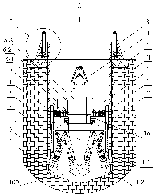
[0033] Example 1, such as Figure 1-2As shown, a caisson shaft tunneling machine includes a tunneling system, a control system and a detection system, and the control system and the detection system are connected with the tunneling system for controlling and detecting the tunneling state. The excavation system includes an excavation device 1 and a well wall pressure lifting device 8. The well wall pressure lifting device 8 is arranged on the wellhead ring beam 10 on the ground, and the well head ring beam 10 is provided with at least two well wall pressure lifting devices. The device 8 and the well wall pressure raising device 8 are equidistantly arranged on the wellhead ring beam 10. The number of the well wall pressure raising device 8 can be set according to the diameter of the wellhead of the originating shaft, whichever can provide a stable support force for the shaft . The excavation device 1 is arranged in the starting shaft 100 and is used for excavating rock and soil...

Embodiment 2

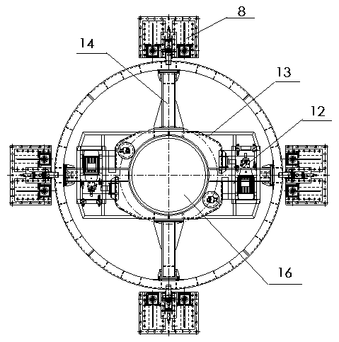
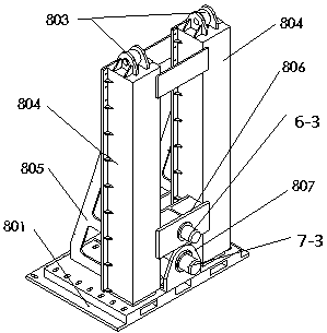
[0036] Example 2, such as Figure 3-4 As shown, a caisson method shaft boring machine, the well wall pressure lifting device 8 includes a bottom plate 801 arranged on the wellhead ring beam 10, two support boxes 802 are arranged on the bottom plate 801, and the inside of the support box 802 is set There is a pressure-lifting oil cylinder 803, which is vertically arranged in the support box, and the pressure-lifting oil cylinder has enough stroke to ensure that the movable bolt has sufficient adjustment space when inserting or pulling out the shaft hole of the segment. The supporting box 802 is provided with a sliding box 804, which cooperates with the supporting box 802. The sliding box is sleeved on the supporting box and slides up and down along the supporting box. The fixed end of the pressure-lifting cylinder 803 is connected with the bottom plate 801 through the cylinder base 805, and the telescopic end of the pressure-lifting cylinder 803 is connected with the slide box ...


PUM


Abstract

The invention discloses a drop-shaft-sinking-based shaft well tunneller and a construction method thereof so that problems of shaft well excavation mechanization, low automation degree and high risk coefficient in the prior art can be solved. The drop-shaft-sinking-based shaft well tunneller comprises a tunneling system, a control system and a detection system. The tunneling system includes an excavation device and a well wall lifting and pressing device. A bottom pipe joint and a guiding base are arranged in a starting shaft well; the bottom pipe joint is arranged below the guiding base; anda driving fixation rack is arranged at the guiding base and the lower part of the driving fixation rack is connected with the bottom pipe joint by a propulsion cylinder. A rotating device is arrangedat the driving fixation rack; a rotation rack is arranged at the lower part of the rotating device; and an excavating device is connected with the rotation rack. A hydraulic pump station, a driving device and a slag discharging device are arranged at the rotating device; and the slag discharging device corresponds to a lifting grab bucket. The drop-shaft-sinking-based shaft well tunneller is a modular shaft well tunneling machine that is used for mechanical excavation and support of a shaft well; the excavation precision and excavation speed of the whole process are improved; the mechanical automatic construction is realized; and the work efficiency and construction safety factor are increased.

Description

technical field [0001] The invention relates to the technical field of tunnel construction, in particular to a caisson shaft boring machine and a construction method thereof. Background technique [0002] Shaft engineering is widely used in the field of underground space development, such as shield launching, receiving shafts, mining shafts, water conservancy engineering shafts, tunnel ventilation shafts, underground fortification shafts, underground three-dimensional garage shafts, etc. At present, manual excavation is still commonly used in shaft excavation. While excavating, the well wall is cast in place or the prefabricated shaft is sunk to form support. The degree of mechanization and automation is generally low, the safety risk of the construction process is high, and the overall construction cost is high. . Contents of the invention [0003] In view of the deficiencies in the above-mentioned background technology, the present invention proposes a caisson shaft bor...

Claims


Application Information

Patent Timeline
IPC IPC(8): E21D1/08
CPCE21D1/08
Inventor 杨聚辉肖威赵飞周倩张瑜峰闫杨义冯琳吕旦吴彦星袁征
Owner CHINA RAILWAY ENGINEERING EQUIPMENT GROUP CO LTD
Why Eureka
Try Eureka