Novel engine without crankshaft and control method thereof

An engine without a crankshaft, which is applied in engine control, engine components, engine cooling, etc., and can solve problems such as the inability of the piston to perform work, affecting the fuel economy of the engine, and high manufacturing costs

Inactive Publication Date: 2019-01-04
ANYANG INST OF TECH
View PDF7 Cites 2 Cited by
  • Summary
  • Abstract
  • Description
  • Claims
  • Application Information

AI Technical Summary

Problems solved by technology

[0003] Due to the limitations of the traditional engine structure, no matter it is a four-stroke engine or a two-stroke engine, it is impossible to pass gas with higher temperature and higher pressure into the space formed under the piston, and the working medium cannot continue to expand to do work on the piston, which is serious. Restricted further improvement of engine combustion efficiency
[0004] On the other hand, because the exhaust gas discharged by the traditional engine still has a relatively high temperature and high pressure, it has a certain potential to do work. Therefore, the exhaust gas turbocharging technology and the compound engine technology are adopted to use the energy of the exhaust gas to drive the turbine to rotate. Increase the intake pressure of the engine or directly transmit the rotational torque of the turbine to the crankshaft

Method used


Image

  • Novel engine without crankshaft and control method thereof
  • Novel engine without crankshaft and control method thereof
  • Novel engine without crankshaft and control method thereof

Examples


Embodiment Construction

[0073] In order to make the purpose, technical solutions and advantages of the present invention more clear, the present invention will be further described in detail below in conjunction with specific embodiments and with reference to the accompanying drawings; it should be understood that these descriptions are only exemplary and not intended to limit the scope of the present invention; As far as general usage is concerned, the most commonly used working state is usually preferred, but it does not rule out the reverse direction, or tilting at a certain angle; in addition, in the following figures and descriptions, descriptions of known structures and technologies are omitted to avoid unnecessarily obscure the concepts of the present invention.

[0074] Below, comprehensive reference Figure 1 to Figure 7 The novel engine of the present invention will be described in detail.

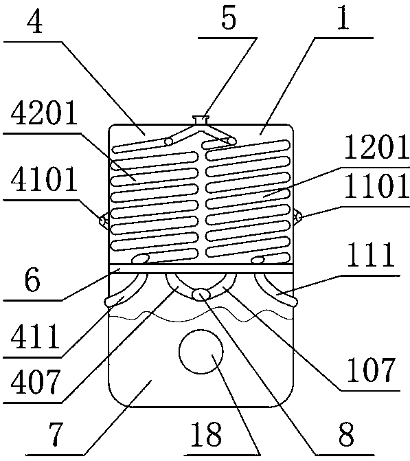
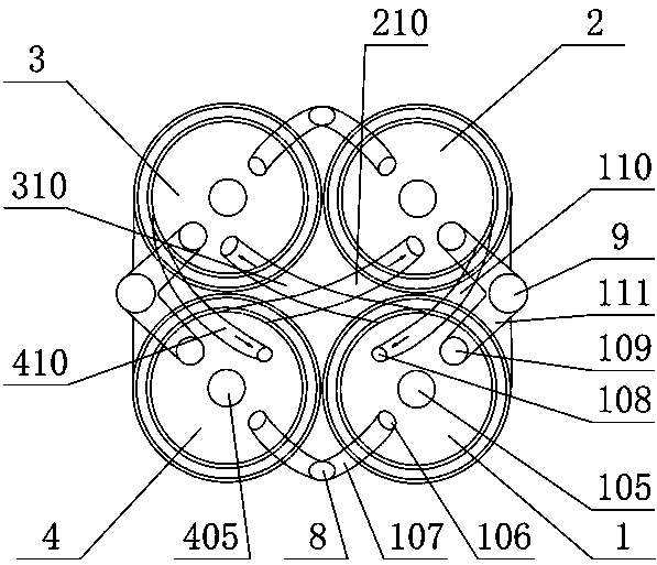
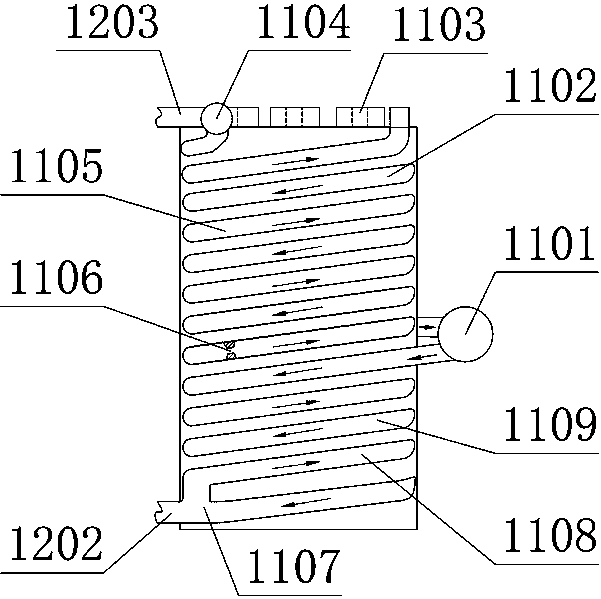
[0075] Such as Figure 1-7 As shown, in the new engine without crankshaft, there are 4 power cylin...


PUM


Abstract

The invention provides a novel engine without a crankshaft. The novel engine is composed of not less than two power cylinders, and includes the power cylinders, secondary expansion gas passages between the power cylinders, an impulse type lubrication system, a fuel injection system, a cylinder body temperature control system, an oxygen injection system, a ventilation system, a starting system, anECU and a power output system. A power cylinder using outputting reciprocating linear motion performed by pistons in the cylinders as a basic function is used as a unit, through the secondary expansion gas passages, exhaust gas in the power cylinder near the end of doing work by combustion expansion is introduced into another power cylinder piston under the compression stroke for secondary expansion work, and the combination of oil cooling and air cooling is adopted, the heat at the tops of the power cylinders is brought to the bottoms of the power cylinders through a double-layer spiral cooling liquid pipe to improve the secondary expansion work capability of the gas to improve the thermal efficiency of the engine, and finally, power output adopts a planetary gear mechanism to convert thereciprocating linear motion into a continuous rotary motion.

Description

technical field [0001] The invention belongs to the field of engines, relates to two-stroke engine technology, and is a two-stroke engine technology for improving engine expansion and working ability and improving engine thermal efficiency. Background technique [0002] How to improve the thermal efficiency of the engine is a research topic with a history of 100 years, and it is also an enduring research hotspot, such as: Atkinson (Atkinson) cycle engine, Miller (Mill) cycle engine, etc. Thermal mode or constant volume exothermic mode to increase the expansion volume of high-temperature and high-pressure gas to realize super-expansion engine cycle. [0003] Due to the limitations of the traditional engine structure, no matter it is a four-stroke engine or a two-stroke engine, it is impossible to pass gas with higher temperature and higher pressure into the space formed under the piston, and the working medium cannot continue to expand to do work on the piston, which is serio...

Claims


Application Information

Patent Timeline
IPC IPC(8): F02B75/02F02B75/18F01M1/08F01P1/02F01P3/02F02D41/30
CPCF01M1/08F01P1/02F01P3/02F01P2001/023F01P2003/022F02B75/02F02B75/18F02B2075/025F02D41/30
Inventor 王俊昌刘近平李军民李松吕掌权刁苏顺
Owner ANYANG INST OF TECH
Why Eureka
Try Eureka