Quasi-zero stiffness vibration isolator with positive and negative stiffness in parallel connection

A technology of quasi-zero stiffness and positive and negative stiffness, applied in the field of low-frequency passive vibration isolation, can solve the problems of jumping vibration isolation transmissibility, affecting vibration isolation effect, excessive static deformation, etc., and achieves compact structure, convenient processing and manufacturing, and easy The effect of maintenance

Active Publication Date: 2019-01-04
XI AN JIAOTONG UNIV
View PDF6 Cites 14 Cited by
  • Summary
  • Abstract
  • Description
  • Claims
  • Application Information

AI Technical Summary

Problems solved by technology

If the external disturbance frequency of the passive vibration isolator is greater than the natural frequency of the vibration isolator system of the controlled object However, when implementing low-frequency vibration isolation for external disturbances such as less than 2 Hz, there will be problems with excessive static deformation and instability, resulting in low-frequency vibration isolation problems
Quasi-zero-stiffness vibration isolation is to realize the reduction of system stiffness under the premise of ensuring the positive stiffness of the system through the parallel structure of positive and negative stiffness, thereby reducing the natural frequency of the system and improving the vibration isolation performance, but this type of quasi-zero-stiffness vibration isolator is positive The stiffness is low and there is nonlinearity, which leads to the jumping phenomenon of the vibration isolation transmissibility, which affects the vibration isolation effect

Method used


Image

  • Quasi-zero stiffness vibration isolator with positive and negative stiffness in parallel connection
  • Quasi-zero stiffness vibration isolator with positive and negative stiffness in parallel connection
  • Quasi-zero stiffness vibration isolator with positive and negative stiffness in parallel connection

Examples


Embodiment Construction

[0018] The present invention will be described in further detail below in conjunction with the accompanying drawings and specific embodiments.

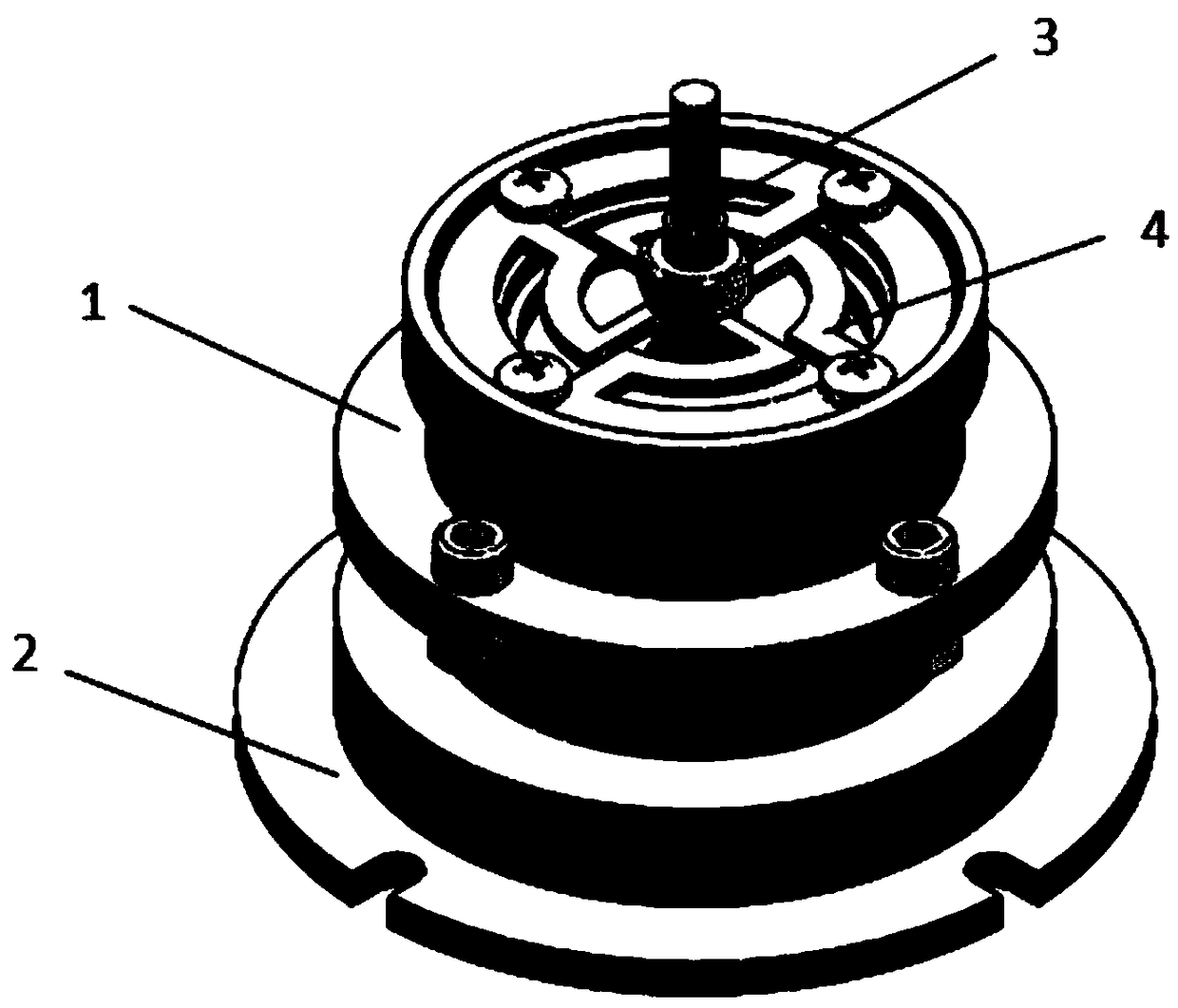
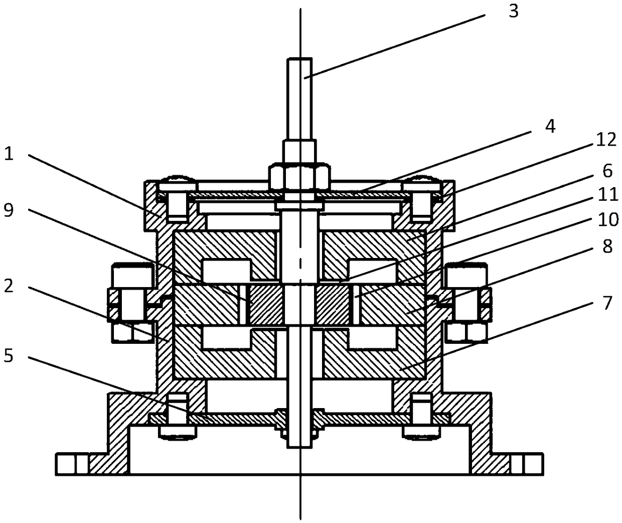
[0019] Such as figure 1 , figure 2 , image 3 , Figure 4 with Figure 5 As shown, a quasi-zero-stiffness vibration isolator with positive and negative stiffnesses in parallel in the present invention includes a top cover 1, a base 2, and a support rod 3. A coil spring 4 connects the support rod 3 to the top cover 1, and the coil spring 4 is connected to the top cover A spacer 12 is installed between 1 for adjusting the vertical position of the coil spring 4. The coil spring 4 is fixedly connected with the upper cover 1 by bolts. The upper end of the support rod 3 passes through the through hole in the middle of the coil spring 4 , and the lower end of the support rod 3 passes through the through hole in the middle of the guide plate 5 . The upper cover 1 and the base 2 are fixedly connected by bolts. When the support rod 3 is...


PUM


Abstract

The invention discloses a quasi-zero stiffness vibration isolator with positive and negative stiffness in parallel connection. The vibration isolator comprises a base, an upper cover, a supporting rod, spiral springs, spacers, an annular iron core, fan-shaped permanent magnet bodies, stators, a permanent magnet body clamping mechanism, working air gaps and a guide plate. The fan-shaped permanent magnet bodies, stators, permanent magnet body clamping mechanism, and working air gaps form a magnetic flow loop, and form magnetic springs with negative magnetic stiffness. The spiral springs are connected with the supporting rod and the upper cover, and initial positive stiffness of the vibration isolator is provided and is in parallel connection with magnetic negative stiffness. The dynamic stiffness of the annular iron core in the equilibrium position is reduced. The guide plate is mounted on the lower portion of the base, and is in sliding-fit with the supporting rod. Compared with an existing quasi-zero stiffness vibration isolator, the vibration isolator has the advantages that load bearing is high, and the mechanism is compact; and as a passive vibration isolator, the vibration isolator can effectively reduce the natural frequency of the vibration isolation system, broaden a vibration isolation frequency band, and has the advantages of easy maintenance and high reliability.

Description

technical field [0001] The invention relates to the technical field of low-frequency passive vibration isolation, in particular to a quasi-zero stiffness vibration isolator with positive and negative stiffness connected in parallel. Background technique [0002] Passive vibration control has been widely used in various engineering fields because it does not require external energy, the device structure is simple, easy to implement, economical and reliable. However, with the development of science and technology, and the increasingly higher requirements for the vibration environment, the vibration characteristics of products and structures, the limitations of passive vibration control are exposed. If the external disturbance frequency of the passive vibration isolator is greater than the natural frequency of the vibration isolator system of the controlled object However, when implementing low-frequency vibration isolation for external disturbances such as less than 2 Hz, pr...

Claims


Application Information

Patent Timeline
Patent Type & Authority Applications(China)
IPC IPC(8): F16F7/00F16F6/00
CPCF16F6/005F16F7/00F16F2222/06F16F2228/066
Inventor 张丰徐明龙田征邵恕宝
Owner XI AN JIAOTONG UNIV
Why Eureka
Try Eureka