A high-efficiency circulating water cooling device for laser engraving machine

A laser engraving machine and circulating water cooling technology, which is applied in laser welding equipment, metal processing machinery parts, manufacturing tools, etc., can solve the problems of short contact time between the water tank and cold air, no use of high-temperature gas, and poor water cooling effect, etc., to achieve improvement Engraving effect, improving cooling effect, and reducing energy consumption

Active Publication Date: 2020-09-11
江苏拓博制冷科技有限公司
View PDF10 Cites 0 Cited by
  • Summary
  • Abstract
  • Description
  • Claims
  • Application Information

AI Technical Summary

Problems solved by technology

However, the contact time of the water tank of this cooling device with the cold air is short, and it is difficult to fully cool the water, resulting in poor water cooling effect. At the same time, the high-temperature gas generated by the vortex tube is not well utilized.

Method used


Image

  • A high-efficiency circulating water cooling device for laser engraving machine
  • A high-efficiency circulating water cooling device for laser engraving machine
  • A high-efficiency circulating water cooling device for laser engraving machine

Examples


Embodiment 1

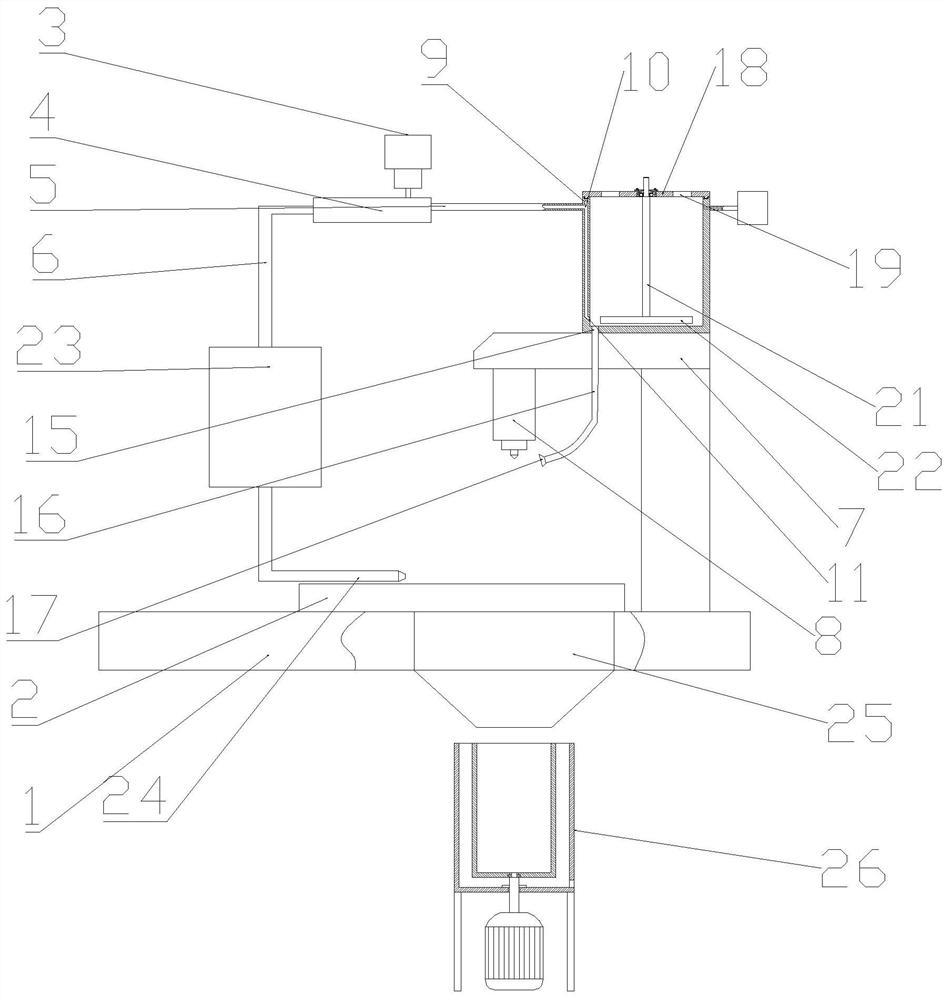
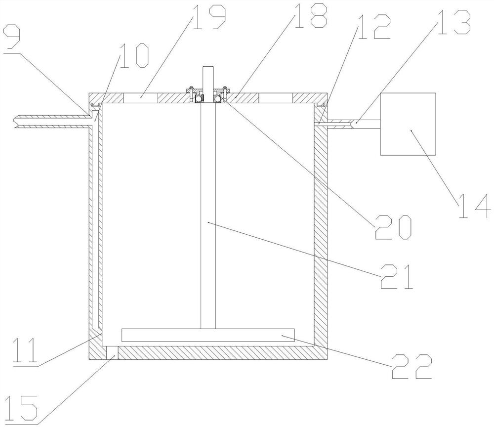
[0017] see figure 1 , figure 2 and image 3 , a high-efficiency circulating water cooling device for a laser engraving machine, comprising a base 1, a workpiece 2, an air compressor 3, a vortex tube 4, a cold air tube 5, a hot air tube 6, a bracket 7 and a laser engraver 8, and the base 1 is placed above There is the workpiece 2, the air compressor 3 is arranged above the workpiece 2, the air compressor 3 communicates with the air inlet of the vortex tube 4, and the cold wind is arranged on the right side of the vortex tube 4 Pipe 5, the hot air pipe 6 is arranged on the left side of the vortex pipe 4, the laser engraver 8 is installed on the bolt below the bracket 7; the right side of the cold air pipe 5 communicates with the cold air inlet 10, and the cold air The inlet 10 is set on the inner wall on the left side of the cooling box 9. The cold air inlet 10 and the bottom of the inner cavity of the cooling box 9 form a cold air outlet 11. Cold air can enter from the cold ...

Embodiment 2

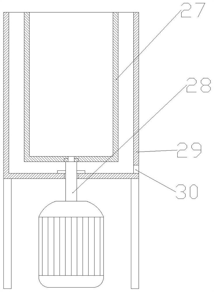
[0019] see Figure 4 Compared with Embodiment 1, this embodiment 2 is only different in that the number of the waste liquid recovery device 26 is greater than one, and another waste liquid recovery device 26 can be replaced to continue filtering after the iron filings in the screen frame 27 are filled. , to facilitate continuous operation.

[0020] The working principle of the present invention is: cold air can enter from described cold air inlet 10, blow out from described cold air outlet 11, be used for cooling the water in described cooling box 9, reach the effect of lowering water temperature; Described cold air outlet 11 places water temperature Lowest, it can directly flow from the water outlet 15 into the cooling pipe 16 for the cooling of the laser engraver 8, making full use of the cooling effect of the cold air, greatly improving the cooling of the laser engraver 8 Effect: the stirring blade 22 is welded and fixed at the bottom of the stirring shaft 21, and the stir...


PUM


Abstract

The invention relates to the technical field of laser engraving, in particular to a laser engraving machine efficient circulation water cooling device comprising a base, a workpiece, an air compressor, a vortex tube, a cold air tube, a hot air tube, a support and a laser engraving device. The right side of the cold air tube communicates with a cold air inlet. A cold air outlet is formed by the cold air inlet and the bottom of an inner cavity of a cooling box. The upper portion of the right side wall of the cooling box is provided with a water inlet. A water outlet is formed in the position, close to the cold air outlet, of the bottom of the cooling box. A cooling tube is clamped in the water outlet. A cover plate is clamped on the upper portion of the cooling box. The lower portion of thehot air tube communicates with a booster pump. The lower portion of the booster pump communicates with a hot air nozzle. The hot air nozzle is tightly attached to the workpiece engraved face. The bottom of the workpiece is provided with a waste liquid outlet. Hot air and cold air generated by the vortex tube are fully utilized, energy is fully utilized, energy consumption during cooling is greatlyreduced, and economic benefits of an enterprise are increased effectively.

Description

technical field [0001] The invention relates to the technical field of laser engraving, in particular to a high-efficiency circulating water cooling device for a laser engraving machine. Background technique [0002] The laser engraving machine uses a focused high-power-density laser beam to irradiate the workpiece, so that the irradiated material is rapidly melted, vaporized, ablated or reached the ignition point, and at the same time, the molten material is blown away by the high-speed airflow coaxial with the beam, so as to achieve the workpiece Engraving technical effect. [0003] Chinese patent (notification number: CN207223196U, announcement date: 2018.04.13) discloses a cooling device for a laser engraving machine, including a laser engraving machine and a cooling device. The laser engraving machine includes a workbench on which a support is provided. There is a laser tube on the seat, the upper end of the laser tube is provided with an air inlet, and the lower end i...

Claims


Application Information

Patent Timeline
Patent Type & Authority Patents(China)
IPC IPC(8): B23Q11/10B23K26/70B23K26/362
CPCB23K26/361B23K26/362B23K26/703
Inventor 刘慧华
Owner 江苏拓博制冷科技有限公司
Why Eureka
Try Eureka