Light beam deflection control method based on liquid crystal optical phased array

A technology of liquid crystal optics and beam deflection, applied in optics, nonlinear optics, instruments, etc., can solve the problems of low tracking bandwidth of the beam pointing precision system, reduce system volume, etc., achieve improved tracking bandwidth and response speed, and reduce system size. Volume, the effect of reducing signal attenuation

Active Publication Date: 2019-01-08
CHANGCHUN UNIV OF SCI & TECH
View PDF7 Cites 11 Cited by
  • Summary
  • Abstract
  • Description
  • Claims
  • Application Information

AI Technical Summary

Problems solved by technology

[0004] In order to solve the problems of low beam pointing accuracy and system tracking bandwidth in the prior art, the present invention provides a beam deflection control method based on liquid crystal optical phased array, and the system optical path built based on the beam deflection control method can reduce the While reducing the volume of the system, it effectively reduces the problem of light loss

Method used


Image

  • Light beam deflection control method based on liquid crystal optical phased array
  • Light beam deflection control method based on liquid crystal optical phased array
  • Light beam deflection control method based on liquid crystal optical phased array

Examples


specific Embodiment approach 1

[0022] Specific implementation mode one, combination Figure 1 to Figure 7 In this embodiment, a method for controlling beam deflection based on a liquid crystal optical phased array is described. The method includes the following steps:

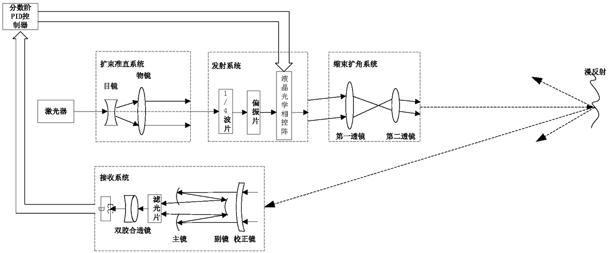
[0023] Step 1. The laser emits a beam of linearly polarized light that passes through the beam expanding collimation system and the emission system to produce linearly polarized light in the same direction as the optical axis of the liquid crystal optical phased array. Diffuse reflection occurs on the measured object;

[0024] Step 2. Use a receiving system to receive the light signal diffusely reflected by the object to be measured and perform light convergence, use a reflex system to reflect the echo laser to the filter, filter the background stray light through the filter, and then glue it together The lens condenses the echo laser onto the photosensitive surface of the CCD detector; the receiving system can effectively reduce the light loss, ...

specific Embodiment approach 2

[0032] Specific implementation mode two, combination figure 1 To describe this embodiment, this embodiment is the beam deflection control system based on the liquid crystal optical phased array beam deflection control method described in the first embodiment, the system includes a beam deflection control system, and the beam deflection control system includes a controller , A beam expanding collimation system, a transmitting system, a reduced beam expanding angle system and a receiving system. The receiving system includes a CCD detector, a double cemented lens, a filter and a reflex system; the transmitting system includes a quarter Wave plate, polarizer and liquid crystal optical phased array; the beam reduction and expansion system includes a first lens and a second lens; the reflex system is composed of a secondary mirror, a primary mirror and a correction mirror placed in sequence, which can be effective Improve the light loss problem.

[0033] The laser emits a beam of line...

specific Embodiment approach 3

[0035] Specific implementation mode three, combination Figure 3 to Figure 7 This embodiment is a simulation example of the beam deflection control method based on the liquid crystal optical phased array described in the first embodiment:

[0036] 1. Establish the transfer function of the liquid crystal optical phased array;

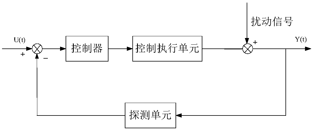
[0037] The liquid crystal optical phased array with drive circuit as the controlled object can be equivalent to the product of a first-order inertia link and a delay link. The first-order inertia link is mainly caused by the relaxation characteristics of liquid crystal molecules. The delay link includes two parts: data transmission from the controller to the driver and data transmission from the driver to the liquid crystal electrode. The transfer function of the liquid crystal phased array beam deflector can be expressed as

[0038]

[0039] Where T 1 Related to the relaxation characteristics of liquid crystal molecules, the value is 0.0025, T 2 Represents t...


PUM


Abstract

The invention discloses a light beam deflection control method based on a liquid crystal optical phased array, relates to the field of liquid crystal optical phased arrays, and aims to solve the problems of low beam pointing precision and low system tracking bandwidth existing in the prior art; a beam of linearly polarized light emitted by a laser passes through a beam expanding collimation systemand an emitting system to generate linearly polarized light; the linearly polarized light is subjected to diffuse reflection on an object to be measured after passing through a beam contracting and angle expanding system; a receiving system receives light signals reflected by the object to be measured in a diffuse reflection mode, and the light signals are converged to the light sensing surface of a CCD detector, and the difference value between the laser spot position and the center of the CCD detector is calculated; an oblique incidence type triangular measuring method is adopted to obtainan actual light beam deflection angle; the error of the actual light beam deflection angle and a set light beam deflection angle is transmitted to a fractional order PID controller, and a liquid crystal optical phased array driving circuit is controlled by the fractional order PID controller to input a proper voltage to the liquid crystal optical phased array, so that the liquid crystal optical phased array generates corresponding phase modulation, and accurate deflection of emergent light beams is realized.

Description

Technical field [0001] The invention relates to the field of liquid crystal optical phased arrays, in particular to a beam deflection control method based on liquid crystal optical phased arrays. Background technique [0002] Liquid crystal optical phased array technology is a non-inertial and fast electronically controlled beam scanning control technology. By applying different voltages to each element of the liquid crystal optical phased array, each element produces a different phase delay, and then changes the incidence. The wavefront phase of the light wave changes the propagation direction of the incident light wave after beam synthesis to achieve beam deflection. Compared with traditional mechanical beam control technology, the liquid crystal optical phased array has the advantages of small size, light weight, fast speed, low power consumption, and no mechanical inertia. It is used in lidar, laser communication, optical information processing, adaptive optics, biological F...

Claims


Application Information

Patent Timeline
Patent Type & Authority Applications(China)
IPC IPC(8): G02F1/29
CPCG02F1/292G02F1/293
Inventor 王春阳牛启凤史红伟李兰婷
Owner CHANGCHUN UNIV OF SCI & TECH
Why Eureka
Try Eureka