
Ku-band dual-polarization radiometer antenna feeder

An antenna feed, dual-polarization technology, used in antennas, waveguide horns, waveguide devices, etc., can solve the problems of excessive metal material density, long manufacturing cycle, and heavy processing device weight, and achieve low 3D printing cost, Good for mass production and good electrical properties

Inactive Publication Date: 2019-01-08
NANJING UNIV OF SCI & TECH
View PDF5 Cites 2 Cited by
  • Summary
  • Abstract
  • Description
  • Claims
  • Application Information

AI Technical Summary

Problems solved by technology

[0003] However, there are three disadvantages in the manufacturing process of traditional microwave and millimeter wave devices: 1. Because the density of the metal material itself is often too high, the weight of the processed device is large, which is not conducive to the assembly of aircraft and satellites and some devices used for experimental testing. Carrying of Microwave Devices
2. The subtractive manufacturing process of traditional CNC milling often produces a large amount of metal consumables, which will greatly increase the cost of mass production of microwave and millimeter wave devices
3. Long manufacturing cycle
When the horn antenna is used as the reflector antenna feed, it is required to have a high phase center stability and an approximately circularly symmetrical primary pattern, while the radiation pattern of the traditional horn antenna feed is different in each plane, E The phase centers of the H plane and the H plane do not coincide, which does not meet the requirements of the symmetrical feed performance of the reflector antenna

Method used


Image

  • Ku-band dual-polarization radiometer antenna feeder
  • Ku-band dual-polarization radiometer antenna feeder
  • Ku-band dual-polarization radiometer antenna feeder

Examples


Embodiment 1

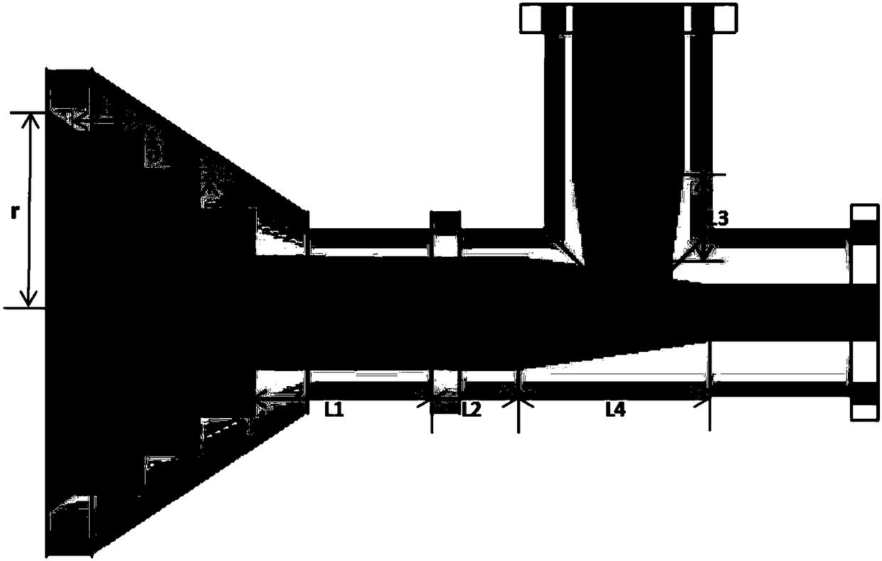
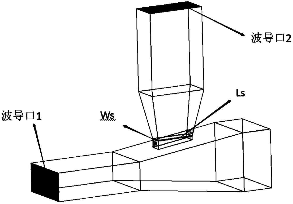
[0034] Such as figure 1 As shown, in this embodiment, the opening angle θ=35o; horn radius R=35.3mm; groove wall thickness d=4.9mm; groove wall spacing m=2mm; groove depth h=12.28mm; square-circle converter length L1=22mm ; The length of the square waveguide L2 = 10.2mm; the length of the pyramid connected with the square waveguide L4 = 37mm; the length of the other pyramid L3 = 24.6mm. Such as figure 2 As shown, in this example, the length Ls=12.5mm and the width Ws=3.9mm of the rectangular opening where the two pyramids intersect. The dimensions of the square waveguide, rectangular waveguide, and circular waveguide ports are those of the Ku-band standard waveguide.

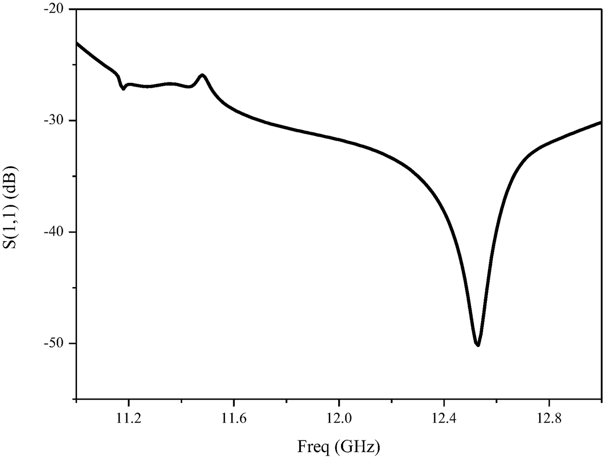
[0035] By simulating the front-end with HFSS software, the return loss of waveguide port 1 can be obtained as follows: image 3 As shown, the return loss of waveguide port 2 is as Figure 4 As shown, the return loss of the two ports in the front-end working frequency band is less than -10dB, S11 is less tha...


PUM


Abstract

The invention discloses a Ku-band dual-polarization radiometer antenna feed, which comprises a corrugated conical horn antenna, a square-circle converter and an orthogonal mode coupler which are integrally connected through 3D printing. The orthogonal mode coupler comprising two orthogonal pyramids, 2 rectangular waveguide and 1 square waveguide, the circular port of the square-circle converter isconnected with the circular port of the corrugated conical horn antenna, the square port is connected to one end of the square waveguide of the orthogonal mode coupler, the other end of the square waveguide of the orthogonal mode coupler is connected with a square port of a horizontal corner pyramid, The rectangular aperture of the horizontal corner pyramid is connected with the first rectangularwaveguide, the vertical corner pyramid is orthogonal to the horizontal corner pyramid in the middle of the horizontal corner pyramid, the intersection is a rectangular aperture, the other end of thevertical corner pyramid is connected with the second rectangular waveguide, and the other waveguide apertures of the two rectangular waveguides are used as output ports respectively. The antenna, theconverter and the coupler of the invention are integrally designed without assembly, and the 3D printing material is light in quality and low in cost.

Description

technical field [0001] The invention relates to the antenna feed source technology, in particular to the Ku-band dual-polarization radiometer antenna feed source. Background technique [0002] The traditional processing method for microwave and millimeter wave devices is a subtractive manufacturing process using CNC (Computerized Numerical Control, computer digital control) milling, and the raw materials used are generally metals with good conductivity, such as copper and aluminum. By constructing some special physical structures (distributed parameter circuits), the functions of lumped circuits can be realized equivalently. Therefore, to realize the function of a microwave device, two conditions must be met. One is that the device must have a specific structural frame, and the other is that the part in contact with electromagnetic waves must be a good conductor with low loss. [0003] However, there are three disadvantages in the manufacturing process of traditional microw...

Claims


Application Information

Patent Timeline
IPC IPC(8): H01Q13/02H01P5/19
CPCH01P5/19H01Q13/0208
Inventor 曹迪吴礼高宗彦彭树生张亚曦
Owner NANJING UNIV OF SCI & TECH
Learn More