Grinding wheel path generation method for tilting-axis single-point grinding of free-form curved surface

A path generation and free technology, applied in the parts of grinding machine tools, grinding automatic control devices, grinding driving devices, etc., can solve the problems of complex and unprovided grinding wheel path planning, and meet the requirements of reducing dynamic response performance, High processing efficiency and the effect of ensuring smoothness

Active Publication Date: 2019-01-11
TIANJIN UNIV
View PDF9 Cites 6 Cited by
  • Summary
  • Abstract
  • Description
  • Claims
  • Application Information

AI Technical Summary

Problems solved by technology

Because this method needs to control two linear axes and two rotary axes of the machine tool at the same time, the planning of the grinding wheel path is very complicated. At present, relevant research at home and abroad, including machine tool suppliers, have not provided relevant calculation methods for the grinding wheel grinding path. Therefore, , it is necessary to develop a grinding wheel path generation method for oblique-axis single-point grinding of free-form surfaces

Method used


Image

  • Grinding wheel path generation method for tilting-axis single-point grinding of free-form curved surface
  • Grinding wheel path generation method for tilting-axis single-point grinding of free-form curved surface
  • Grinding wheel path generation method for tilting-axis single-point grinding of free-form curved surface

Examples


Embodiment 1

[0086] freeform surface

[0087]

[0088]

[0089] Among them, R x =6.2702;

[0090] R y =5.7235;

[0091] K=-0.9988;

[0092] A 4 = 1.927455E-04;

[0093] A 6 = 1.421518E-06;

[0094] A 8 = 1.407505E-07;

[0095] A 10 = -2.036962E-08;

[0096] A 12 ~A 20 =0.

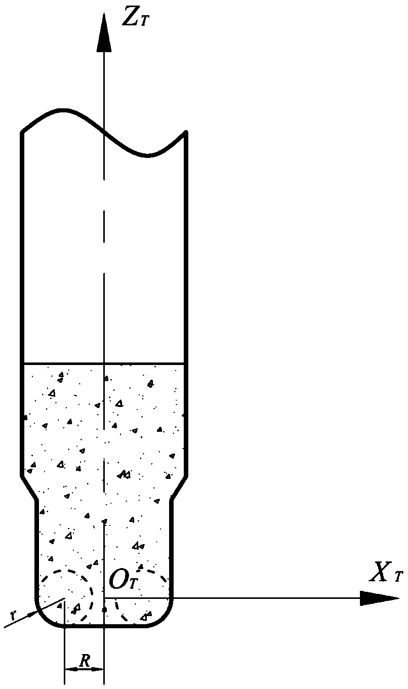
[0097] For example, the free-form surface is ground with a rounded cylindrical grinding wheel with R=1.0mm and r=0.2mm, and the pitch of the equidistant helix is ​​set to 0.5mm. According to the grinding wheel path planning method in the embodiment of the present invention, the corresponding relationship between the X coordinate and the Z coordinate of the grinding wheel control point and the C-axis rotation angle θ is as follows: Figure 5 As shown, the dotted line in the figure represents the X coordinate of the tool control point, and the solid line represents the Z coordinate. In order to ensure that the contact point between the grinding wheel and the workpiece remains unchanged on the grindin...


PUM


Abstract

The invention relates to a grinding wheel path generation method for tilting-axis single-point grinding of a free-form curved surface. The method comprises the steps that a plane perpendicular to theZ axis of a workpiece coordinate system is established at the position zd by a certain distance above the free-form curved surface to be processed in the workpiece coordinate system, an equidistant spiral line is generated in the plane and discretized, points are converted into cylindrical-coordinate system forms (rho, theta and zd) after discretization, the free-form curved surface to be processed is rotated by the angle theta around the Z axis, the minimum distance delta and the B-axis rotation angle beta between the grinding wheel processing curved surface and the rotated free-form curved surface to be processed at each point of the equidistant spiral line in the Z direction are obtained, then coordinates (rho, 0 and zd-delta) of a grinding wheel control point are obtained, specifically, a grinding wheel is a circular-bead columnar grinding wheel, and the inclination angle between the grinding wheel axis and the workpiece rotation shaft axis is beta and changes along with rotation of a workpiece so that it can be ensured that the contact point of the workpiece and the grinding wheel is kept unchanged. According to the method, the projection drive track of the grinding wheel control point is optimally generated, smoothness of feeding motion of the grinding wheel in the X direction is ensured, and the requirement for dynamic response performance of a machine tool is reduced; and meanwhile, as the grinding point of the grinding wheel is kept unchanged, the contour error of the grinding wheel cannot be copied to the workpiece, and accordingly the quality of the processing surface can be further improved.

Description

technical field [0001] The invention belongs to the technical field of ultra-precision machining and complex parts manufacturing, and relates to a method for generating a grinding wheel path for inclined-axis single-point grinding free-form surfaces. Background technique [0002] As a variety of high-precision, high-integration, and miniaturized optoelectronic products continue to emerge in the optical electronics, aerospace, laser, and communication industries, the demand for tiny glass aspheric surfaces and optical free-form surfaces is growing rapidly. For example, the tiny plastic optics that dominate mobile digital cameras are gradually being replaced by glass optics. Compared with plastics, glass has obvious advantages in optical applications. In addition to higher clarity and refractive index, glass also has superior thermal and mechanical stability. [0003] Plastic lenses are generally mass-produced by injection molding, and high-precision molds for injection moldi...

Claims


Application Information

Patent Timeline
Patent Type & Authority Applications(China)
IPC IPC(8): B24B13/00B24B47/20B24B49/00B24B51/00
CPCB24B13/00B24B47/20B24B49/00B24B51/00
Inventor 闫广鹏房丰洲
Owner TIANJIN UNIV
Why Eureka
Try Eureka