A diffuse optical tomography system

An imaging system and optical tomography technology, applied in the field of diffuse optical tomography system, can solve the problems of increasing data acquisition time, reducing system efficiency, increasing system complexity, etc., so as to reduce the complexity of fiber arrangement and improve data acquisition. Efficiency and the effect of improving the detection effect

Active Publication Date: 2020-02-18
XIDIAN UNIV
View PDF8 Cites 0 Cited by
  • Summary
  • Abstract
  • Description
  • Claims
  • Application Information

AI Technical Summary

Problems solved by technology

Among them, since the linear translation stage is a mechanical device, using two linear translation stages as the device for switching the excitation position and the receiving position, errors will inevitably occur during the movement process, which will affect the transmission of optical signals and cause serious optical signal attenuation; Although the use of separated optical fibers reduces the mutual influence, it is not conducive to the increase of detection points and increases the complexity of the system
At the same time, due to the inability to perform multi-channel simultaneous measurement, the data acquisition time is doubled, the system efficiency is reduced, and for young women with high breast density, the detection results are not ideal and have ionizing radiation.

Method used


Image

  • A diffuse optical tomography system
  • A diffuse optical tomography system
  • A diffuse optical tomography system

Examples


Embodiment 1

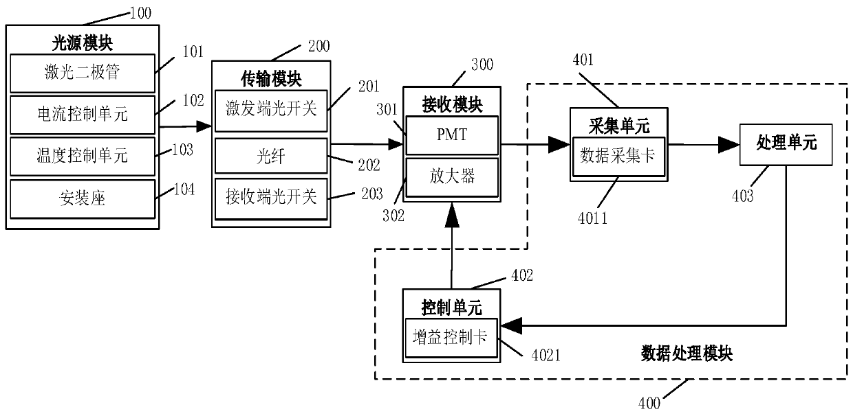
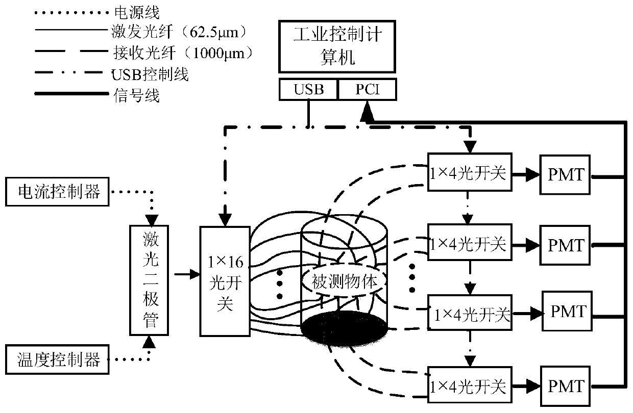
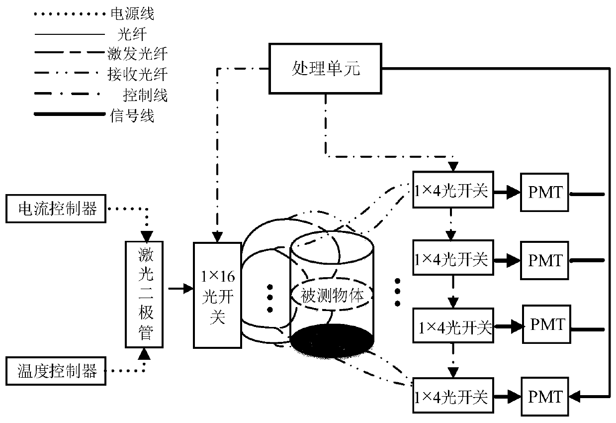
[0046] See figure 1 and image 3 , figure 1 A schematic diagram of a module structure of a diffuse optical tomography system provided by an embodiment of the present invention, image 3 It is a schematic structural diagram of a diffuse optical tomography system provided by an embodiment of the present invention.

[0047] A diffuse optical tomography system, comprising: a light source module 100 , a transmission module 200 , a receiving module 300 , and a data processing module 400 .

[0048] The light source module 100 is used to generate a first light signal to irradiate the measured object;

[0049] Wherein, the light source module 100 includes a laser diode 101 , a current controller 102 , a temperature controller 103 and a mount. The light source module 100 is preferably a laser kit with a wavelength of 785nm.

[0050] Wherein, the first optical signal in this embodiment is the laser signal emitted by the laser diode 101 , the laser diode 101 is preferably a pigtail...


PUM


Abstract

The invention relates to a diffuse optical tomography system, comprising a light source module, a transmission module, a receiving module and a data processing module, wherein the light source moduleis configured to generate a first optical signal; the transmission module is connected with the light source module and used for transmitting the first optical signal and a second optical signal, andthe second optical signal is formed by irradiation of a to-be-detected object by the first optical signal; the receiving module is connected with the transmission module and used for converting the second optical signal into an electrical signal; and the data processing module is connected with the receiving module and used for converting the electrical signal into a digital signal and then processing the digital signal. According to embodiments of the invention, an excitation-reception two-in-one optical fiber is utilized, so the number of optical fibers is decreased, the complexity of optical fiber arrangement is lowered, and data acquisition efficiency is improved; a receiving end optical switch is arranged at a receiving end, so the number of PMTs is decreased and system cost is reduced; and the switching of the receiving end optical switch is controlled by a processing unit so as to realize simultaneous acquisition of multi-channel data, so detection effect is improved.

Description

technical field [0001] The invention belongs to the field of molecular imaging, and in particular relates to a diffusion optical tomography imaging system. Background technique [0002] Diffuse Optical Tomography (DOT), also known as Diffuse Optical Tomography (DOT), is a three-dimensional functional imaging method for thick tissue that is irradiated with near-infrared light. Its goal is to develop a highly sensitive near-infrared The photon detection instrument and the image reconstruction technology based on the photon transport model of biological tissue invert the three-dimensional distribution of the internal optical characteristic parameters of the tissue from the time, space and spectral distribution measurement information of the surface diffused light under multi-point excitation, and make it consistent with the The physiological state of the tissue (hemoglobin concentration, oxygen saturation, etc.) is correlated. DOT is specific, dynamic and sensitive to changes ...

Claims


Application Information

Patent Timeline
Patent Type & Authority Patents(China)
IPC IPC(8): G01N21/359A61B5/00
CPCA61B5/0073G01N21/359
Inventor 朱守平马小雅曹旭马骋陈睿博王民
Owner XIDIAN UNIV
Why Eureka
Try Eureka