An electromagnetic shielding structure of a photomultiplier tube

A technology of electromagnetic shielding structure and photomultiplier tube, which is applied in electron multiplier tube, discharge tube, tube/lamp screen manufacturing, etc., to achieve the effect of simple packaging process, reduced thickness of packaging shielding layer, and reliable shielding effect

Active Publication Date: 2019-01-11
JIANGSU SINOGRAM MEDICAL TECH CO LTD
View PDF2 Cites 2 Cited by
  • Summary
  • Abstract
  • Description
  • Claims
  • Application Information

AI Technical Summary

Problems solved by technology

[0005] In order to solve the problems of shielding and size control of photomultiplier tubes in the prior art, the purpose of the present invention is to reduce the thickness of the packaging shielding layer without affecting the electromagnetic shielding effect, so that the packaging process is simpler and the shielding effect is more reliable

Method used


Image

  • An electromagnetic shielding structure of a photomultiplier tube
  • An electromagnetic shielding structure of a photomultiplier tube
  • An electromagnetic shielding structure of a photomultiplier tube

Examples


Embodiment 1

[0063] This embodiment provides an electromagnetic shielding structure of a photomultiplier tube, such as figure 1 As shown, the electromagnetic shielding structure of the photomultiplier tube includes:

[0064] The periphery of the tube body of the photomultiplier tube is sequentially provided with a shielding layer and an insulating layer; the shielding layer is a single-layer structure made of permalloy material.

[0065] The shielding layer is in contact with the pipe wall of the pipe body to shield the pipe body from electric and magnetic fields, and the insulating layer wraps the shielding layer to encapsulate and isolate the shielding layer from the outside world. The electrical isolation ensures the shielding effect of the shielding layer.

[0066] The shielding layer is connected to the corresponding pins of the photomultiplier tube, for example, for a photomultiplier tube that uses a positive high voltage, the above shielding layer is connected to the ground pin of ...

Embodiment 2

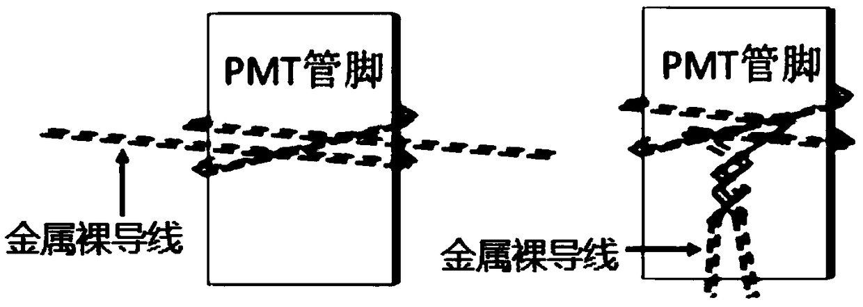
[0073] combine Figure 2A with Figure 2B As shown, the present embodiment provides a method for setting the potential of the shielding layer of a photomultiplier tube, which may include the following steps:

[0074] S1. Select a bare metal wire for fixing the potential of the shielding layer.

[0075] Generally, wires with a thinner diameter have less influence on the thickness of the package. In this embodiment, thin bare metal wires with a diameter of less than 50 microns are preferred.

[0076] S2, tie the middle area of ​​the bare metal wire to the ground pin (positive high voltage) / high voltage pin (negative high voltage) of the photomultiplier tube; stick the two ends of the bare metal wire to the body of the photomultiplier tube on the pipe wall.

[0077] see Figure 2A In the binding method shown, wrap the middle area of ​​the bare metal wire around the ground pin (positive high voltage) / high voltage pin (negative high voltage) three times, and one of the three ci...

Embodiment 3

[0093] In this embodiment, a wire setting method for fixing the potential of the shielding layer of the photomultiplier tube is provided, including:

[0094] M1. Select the bare metal wire used to fix the potential of the shielding layer;
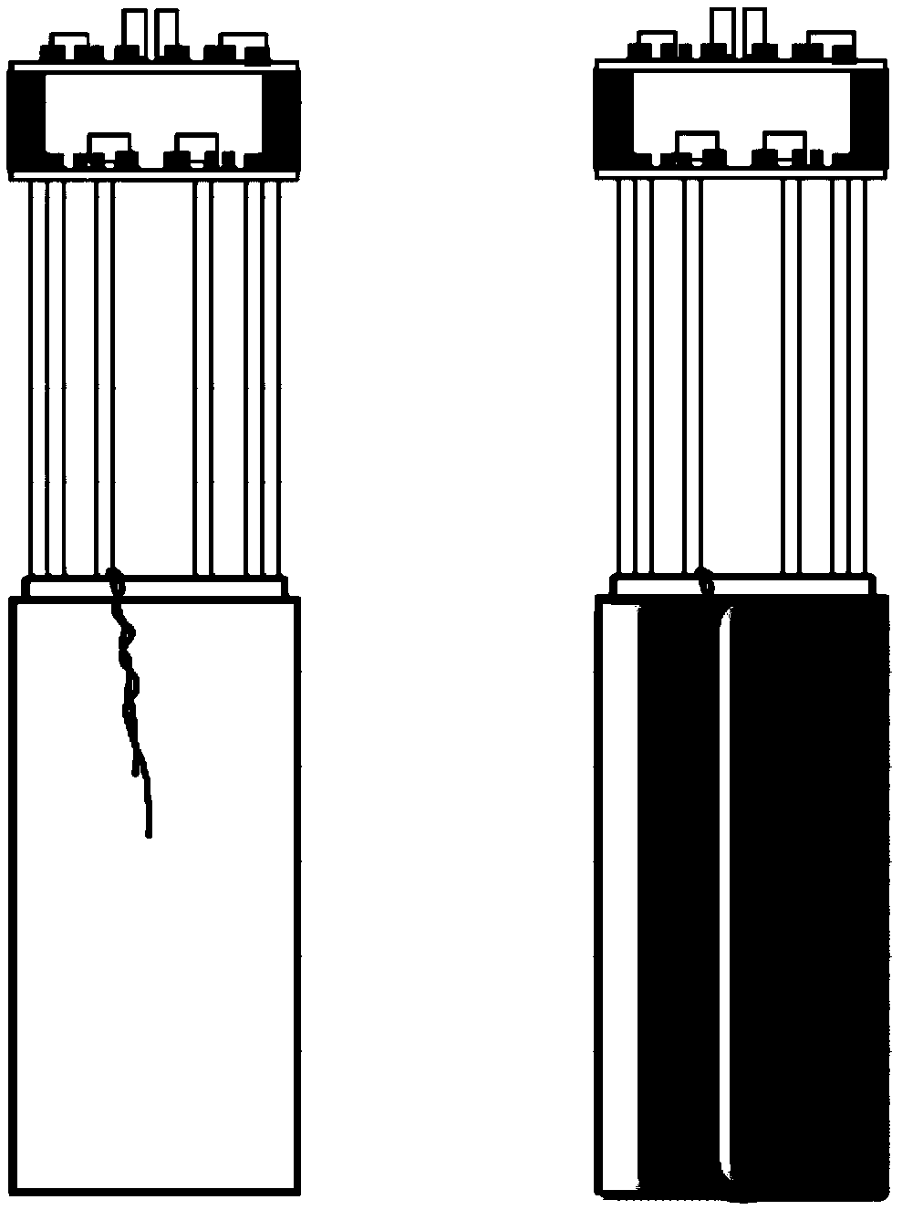
[0095] M2, tie the middle area of ​​the bare metal wire to the ground pin (positive high voltage) / high voltage pin (negative high voltage) of the photomultiplier tube; stick the two ends of the bare metal wire to the body of the photomultiplier tube On the pipe wall, so that the metal bare wire pasted on the pipe wall is connected to the shielding layer;

[0096] Wherein, the middle area of ​​the bare metal wire goes around the pin several times, and the two taps are compressed by the wire when the wire is tightened;

[0097] Cross-twist the two ends of the bare metal wire into a rope and extend towards the pipe wall, and fix the rope-shaped wire on the pipe wall with double-sided adhesive;

[0098] M3. Use conductive silver paint to fix ...


PUM


Abstract

The invention provides an electromagnetic shielding structure of a photomultiplier tube, comprising the following steps: a shielding layer and an insulating layer are sequentially arranged on the periphery of the tube body of the photomultiplier tube. The shielding layer is in contact with the pipe wall of the pipe body to shield the electric field and the magnetic field of the pipe body, and theinsulating layer wraps the shielding layer to encapsulate and isolate the shielding layer. The shielding layer is connected with the corresponding pin of the photomultiplier tube, and the shielding layer is a single layer structure made of permalloy material. The structure can reduce the thickness of the encapsulation shielding layer without affecting the electromagnetic shielding effect, so thatthe encapsulation process is more simple and the shielding effect is more reliable.

Description

technical field [0001] The invention relates to a photomultiplier tube packaging technology, in particular to an electromagnetic shielding structure of a photomultiplier tube. Background technique [0002] Photomultiplier tube is a kind of photodetection device with mature technology and widely used. It is widely used in photon counting, extremely weak light detection, chemiluminescence, bioluminescence research, extremely low energy ray detection, spectrophotometer, polarimeter, colorimeter , Illuminance meter, dust meter, turbidimeter, optical density meter, thermoluminescence meter, radiation calorimeter, scanning electron microscope, biochemical analyzer and other instruments and equipment. [0003] The photomultiplier tube itself is a photosensitive vacuum device with extremely high sensitivity and ultra-fast time response. Its structure and working principle determine that the device itself is extremely sensitive to electric and magnetic fields. When many photomultipli...

Claims


Application Information

Patent Timeline
Patent Type & Authority Applications(China)
IPC IPC(8): H01J43/28H01J9/20
CPCH01J9/20H01J43/28
Inventor 吴和宇吕绮雯
Owner JIANGSU SINOGRAM MEDICAL TECH CO LTD
Why Eureka
Try Eureka