Power factor corrector with active power decoupling function and its control method

A power factor correction and control method technology, applied in the electric power field, can solve the problems of discontinuous current on the DC side of a diode full-bridge rectifier, the output side of the converter cannot be directly connected to a load device, and the negative impact on the power quality of the AC side, etc., to achieve a control method. Simple and reliable, avoid command generation and tracking, improve system reliability

Active Publication Date: 2021-01-19
XI AN JIAOTONG UNIV
View PDF4 Cites 0 Cited by
  • Summary
  • Abstract
  • Description
  • Claims
  • Application Information

AI Technical Summary

Problems solved by technology

However, there is an inherent problem in the single-phase AC-DC energy conversion system: the instantaneous power injected into the converter from the AC grid side includes the power fluctuation component of twice the power frequency in addition to the stable DC power component
The power fluctuation of twice the power frequency will cause the output voltage on the DC side of the converter to produce obvious double power frequency voltage ripple, so the output side of the converter cannot be directly connected to the load device
(Existing literature Yao Sun, Yonglu Liu, Mei Su, Wenjing Xiong and Jian Yang, "Review of Active Power Decoupling Topologies in Single-Phase Systems". IEEE transactions on power electronics, vol.31, no.7, pp:4778-4794 , July 2016) Most of the power factor correction converters that can provide active power decoupling function at this stage are step-down converters, which are characterized by the discontinuous current on the DC side of the diode full-bridge rectifier. On the one hand, the filter of the AC measurement The design becomes complicated and difficult. On the other hand, it leads to high subharmonic content of the current switch on the AC side, which has a certain degree of negative impact on the power quality of the AC side.

Method used


Image

  • Power factor corrector with active power decoupling function and its control method
  • Power factor corrector with active power decoupling function and its control method
  • Power factor corrector with active power decoupling function and its control method

Examples


Embodiment Construction

[0031] The present invention will be described in detail below in conjunction with the accompanying drawings and specific embodiments.
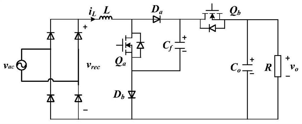
[0032] The key idea of ​​the present invention is to add power MOSFETs, diodes and capacitive elements to the topology of the original power factor correction converter, and transfer the power fluctuations to the snubber capacitor C through the modeling and control of the converter f On the AC side, the power factor correction on the AC side and the stable output voltage on the DC side are realized.

[0033] Such as figure 1 As shown, a circuit topology of a non-isolated single-stage step-up power factor correction converter that can realize active power decoupling, including the input power supply v ac , a set of diode full-bridge rectifiers, two MOSFET power tubes Q a and Q b , two diodes D a and D b , snubber capacitor C f , the output capacitance C o , an inductor L and a load resistor R. Where MOSFET power tube Q a , Diode D a ...


PUM


Abstract

The invention discloses a power factor corrector with an active power decoupling function and a control method thereof, Based on the current topology of step-up power factor correction converter, a buffering circuit is added to control the AC side current waveform and DC side output voltage directly, and the power fluctuation of double power frequency is transferred to the buffering capacitor automatically. The control objectives of correcting power factor and stabilizing output voltage are realized. The requirement of the converter for capacitor device is effectively reduced and the electrolytic capacitor is replaced by thin film capacitor, so the power density, service life and reliability of the converter are improved. At the same time, the proposed converter is based on step-up topology, and the DC-side current of diode full-bridge rectifier is continuous. Compared with the converter based on step-down topology and step-up-buck topology, the proposed converter has the advantages oflower AC-side high-frequency harmonic components and simplified filter design.

Description

technical field [0001] The invention belongs to the field of electric power technology, and in particular relates to a power factor corrector with an active power decoupling function and a control method thereof. Background technique [0002] Single-phase AC-DC converter, as an interface device between single-phase AC grid and DC load, undertakes the responsibility of single-phase AC-DC power conversion and provides stable energy for electrical equipment, and has a wide range of applications in modern social life. In order to ensure the power quality of the single-phase AC grid, the single-phase AC-DC converter often needs to have the ability to realize power factor correction, and eliminate the low-order harmonics of the AC current while ensuring that the fundamental wave of the grid-side AC current is in phase with the AC voltage ingredients. However, there is an inherent problem in the single-phase AC-DC energy conversion system: the instantaneous power injected into the...

Claims


Application Information

Patent Timeline
Patent Type & Authority Patents(China)
IPC IPC(8): H02M1/42H02M1/12H02M7/217
CPCH02M1/12H02M1/4225H02M7/217Y02B70/10
Inventor 张岩丁恺诚刘进军张金水
Owner XI AN JIAOTONG UNIV
Why Eureka
Try Eureka