
A general psk modulation and demodulation system

A modulation and demodulation and demodulator technology, applied in the field of general PSK modulation and demodulation systems, can solve the problems of rising product costs, inability to form scale benefits, and single equipment functions.

Active Publication Date: 2020-12-11
法纳通电器(上海)有限公司
View PDF9 Cites 0 Cited by
  • Summary
  • Abstract
  • Description
  • Claims
  • Application Information

AI Technical Summary

Problems solved by technology

However, the high cost of hundreds of thousands or millions is unbearable for test equipment, and it can only be used as experimental equipment.
Now some universities and companies in China have also begun to develop boards and equipment in this area, but the functions of such equipment are relatively single, and they can only work under fixed modulation and demodulation mode, symbol rate and carrier frequency
In the development of test equipment, for the different parameter requirements of test equipment, there is no universal and cost-effective modulation and demodulation test platform, and high-efficiency solutions for project design and development. Only the expensive foreign general-purpose models can be selected. Domestic modem boards with a single product or performance, in the process, the procurement cycle becomes longer and the product cost rises sharply, seriously affecting product development and delivery
At the same time, in such a development mode of modem test equipment, different test parameter requirements make the development parameters of test equipment different, making the development of each test equipment independent of each other, unable to form economies of scale, and difficult to master core technologies

Method used


Image

  • A general psk modulation and demodulation system

Examples


Embodiment Construction

[0029] In order to enable those skilled in the art to better understand the technical solution of the present invention, its specific implementation will be described in detail below in conjunction with the accompanying drawings:

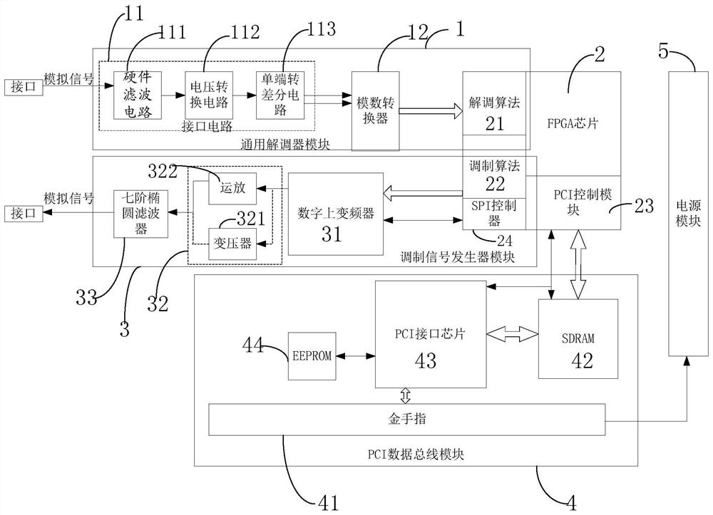
[0030] see figure 1 , the preferred embodiment of the present invention, a kind of general PSK modulation and demodulation system, comprises general demodulator module 1, FPGA chip 2, modulated signal generator module 3, PCI data bus module 4 and power supply module 5.

[0031] The universal demodulator module 1 includes an interface circuit 11 and an analog-to-digital converter 12. The interface circuit 11 includes a hardware filter circuit 111, a voltage conversion circuit 112 and a single-ended to differential circuit 113. The hardware filter circuit and the voltage conversion circuit respectively adopt an S-K filter circuit , The S-K filter circuit can be designed as a high and low pass filter, a band pass filter and a voltage divider circuit ac...


PUM


Abstract

The present invention discloses a universal PSK (phase shift keying) modulation and demodulation system. The system comprises a universal demodulator module, an FPGA (Field-Programmable Gate Array) chip, a modulation signal generator module, a PCI (Peripheral Component Interconnect) data bus module and a power module. The universal demodulator module comprises an interface circuit and an analog-digital converter, the interface circuit comprises an S-K filtering circuit, a voltage conversion circuit and a single-end-to-difference circuit; the FPGA chip is internally provided with a demodulationalgorithm module, a modulation algorithm module, a PCI control module and an SPI (Serial Peripheral Interface) controller; the modulation signal generator module comprises a digital upper converter,a signal output circuit and a seven-order elliptic filter; the PCI data bus module comprises a golden finger circuit board, an SDRAM (Synchronous Dynamic Random Access Memory) chip, a PCI interface chip and an EEPROM (Electrically Erasable Programmable Read-Only Memory); and the power module is connected with the golden finger circuit board. The universal PSK modulation and demodulation system canachieve rapid design and automatic code generation of the demodulation system so as to enhance the universality of the modulation and demodulation system.

Description

technical field [0001] The invention relates to a general PSK modulation and demodulation system. Background technique [0002] In foreign countries, discussions and reports on digital demodulation systems appeared in the 1980s, and digital demodulation design ideas based on System On Chip (SOC) and software radio technology gradually appeared after the 1990s. Some companies have launched digital demodulation products one after another. In 2007, Pentek of the United States successfully launched the powerful Model 7142-428 software radio processor, which not only includes 14-bit 125MHz 4 AD and 1 DA conversion channels, but also designs a multi-band digital down-conversion core , which can realize the extraction range of 2-65536, and also has an interpolation filter with an interpolation range of 2-32768; a series of software wireless processor products launched by Pentek provide superior solutions for wireless communication and other systems. In the research and developmen...

Claims


Application Information

Patent Timeline
Patent Type & Authority Patents(China)
IPC IPC(8): H04L27/20H04L27/22
CPCH04L27/20H04L27/22
Inventor 迟英昊袁鹏孙玮泽左敬轩闫旭东李荣正陈学军戴国银
Owner 法纳通电器(上海)有限公司
Learn More