

A syringe and automatic injection system
An automatic injection and syringe technology, applied in the field of medical devices, can solve problems such as possible pinching of muscles and subcutaneous tissue, potential safety hazards, and whitening of the skin, and achieves a high degree of automation, strong versatility, and strong applicability. Effect
- Summary
- Abstract
- Description
- Claims
- Application Information
AI Technical Summary
Problems solved by technology
Method used
Image

Examples
Embodiment 1
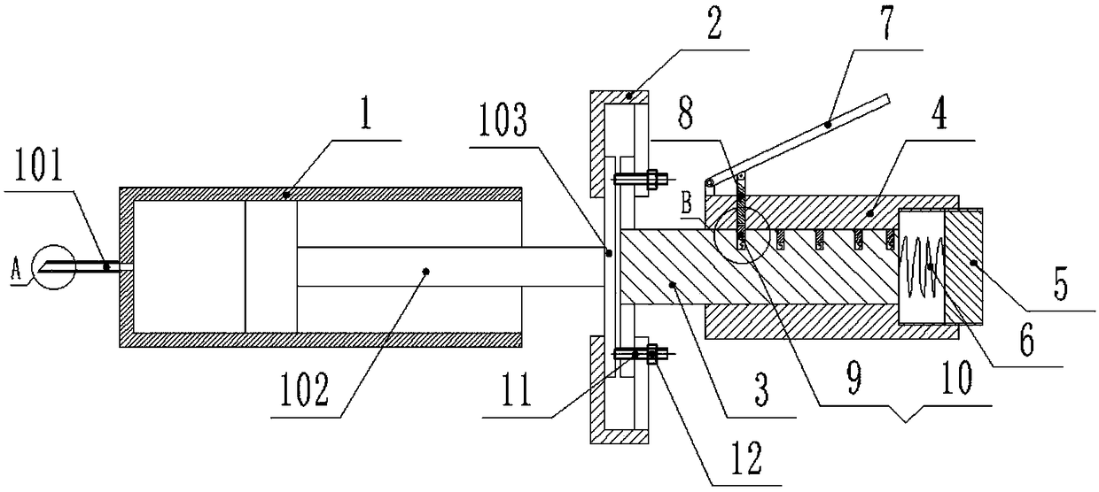
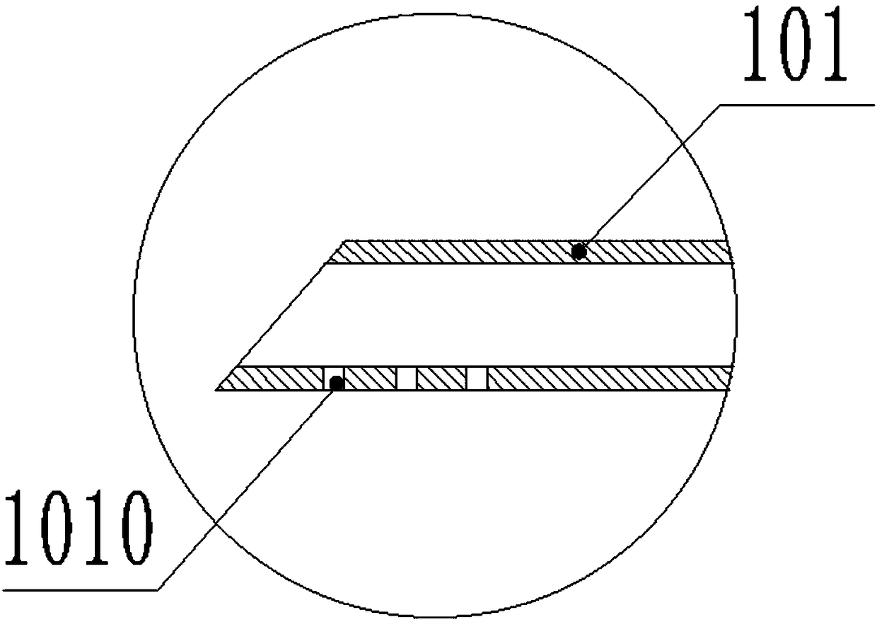
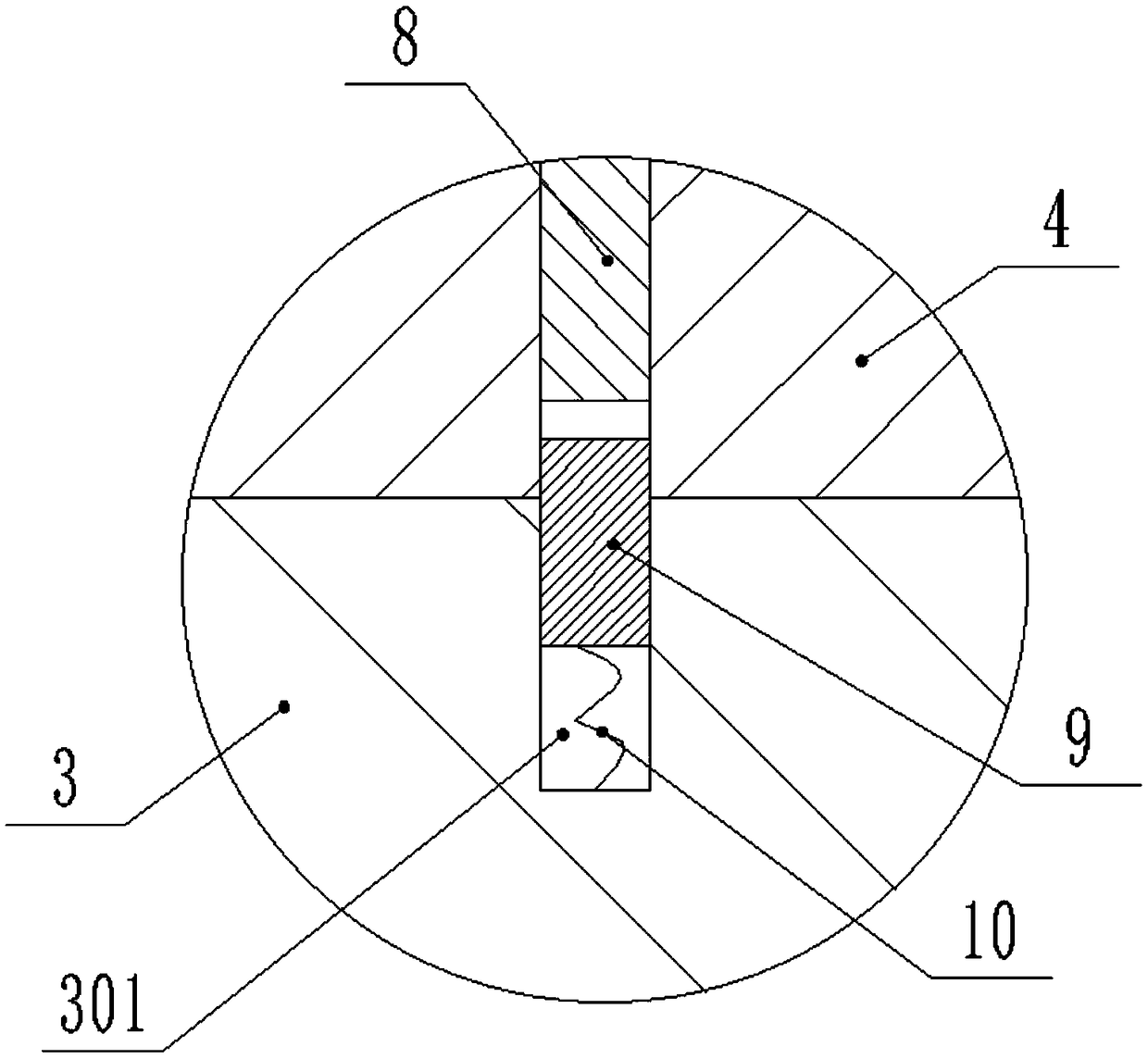
[0031] Such as figure 1 It is a schematic structural diagram of the syringe of the present invention; figure 2 for figure 1 Enlarged view of A; image 3 for figure 1 Enlarged view of B; Figure 4 It is a structural schematic diagram of the quantitative device of the present invention; Figure 5 for Figure 4 C-C sectional view of ; Figure 6 It is a structural schematic diagram of the chuck of the present invention. The above figures focus on clearly expressing the technical solution of this embodiment.
[0032] Such as Figure 1-6 As shown, a syringe provided in this embodiment includes a syringe body 1 and a dosing device, and the dosing device includes a chuck 2, a T-shaped bar 3, a transparent outer cylinder 4, a plug 5, an engaging assembly and a pressing part; The pressing component includes a pressing plate 7 and a pressing bar 8 ; the engaging assembly includes a first spring 10 and a slider 9 .
[0033] The T-shaped head 30 of the T-shaped rod 3 is connecte...
Embodiment 2
[0047] Such as Figure 7 , 8 As shown, this embodiment provides an automatic injection system, including an automatic feeding device and the syringe; the automatic feeding device includes a hoop, a motor (not shown in the figure) and an output shaft 18 installed on the motor The gear 17 on the top; the hoop includes a left half hoop 13 and a right half hoop 14 that is matched and locked with the left half hoop 13; the left half hoop 13 is connected with the plug 5; The right half hoop 14 extends outwards with a moving rod 15 ; the moving rod 15 is provided with a rack 16 meshing with the gear 17 . Wherein the left half hoop 13 is provided with an internal thread blind hole, and the plug 5 is detachably connected with the left half hoop 13 threads. The moving bar 15 is welded or integrally manufactured with the right half hoop 14. The left half hoop 13 and the right half hoop 14 are detachably connected through bolts 17 and lock nuts 18 .
[0048] The working principle of t...
PUM
 Abstract
Description
Claims
Application Information