
Drilling buffering adjustable support for mining

An adjustable drilling platform technology, which is applied in the direction of drilling equipment, earthwork drilling, support devices, etc., can solve the problems of unfixed support, potential safety hazards, and inconvenient adjustment of positions, etc., and achieves simple structure, convenient and reliable use , to avoid the effect of positioning offset

Inactive Publication Date: 2019-01-15
徐志华
View PDF7 Cites 0 Cited by
  • Summary
  • Abstract
  • Description
  • Claims
  • Application Information

AI Technical Summary

Problems solved by technology

[0003] Notification number: The patent document of CN 108104810 A provides a lifting type mining machine support, but in actual use, the advantage of the lifting type mining machine support provided by the above document is that by setting the universal direction at the bottom of the mining machine support Wheels are used to facilitate the displacement of the entire rack, that is, to facilitate the movement of the mining machine. At the same time, there is a retractable fixed bracket on one side of the bracket. The fixed feet at the bottom of the fixed bracket can stably fix the rack on the ground to prevent the equipment from The equipment shifts or collapses during operation. The problem is that the fixing method of the bracket is not firm, which poses a safety hazard. In addition, it is not convenient to adjust the position. In addition, there is no buffer for the drilling machine, and it is easy to shift during the drilling process. Therefore, the invention It is necessary to have an adjustable support for drilling buffer in mining

Method used


Image

  • Drilling buffering adjustable support for mining
  • Drilling buffering adjustable support for mining
  • Drilling buffering adjustable support for mining

Examples


Embodiment Construction

[0020] The technical solution of this patent will be further described in detail below in conjunction with specific embodiments.

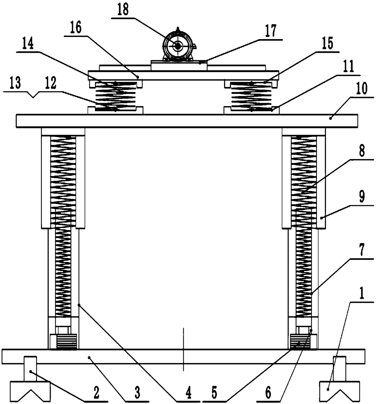
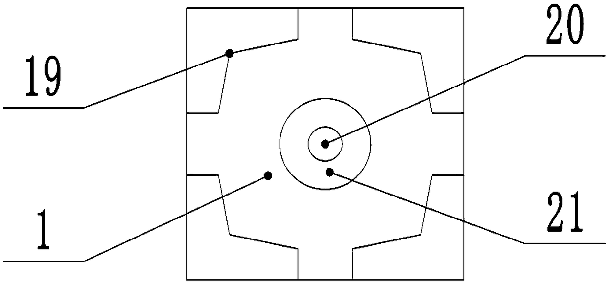
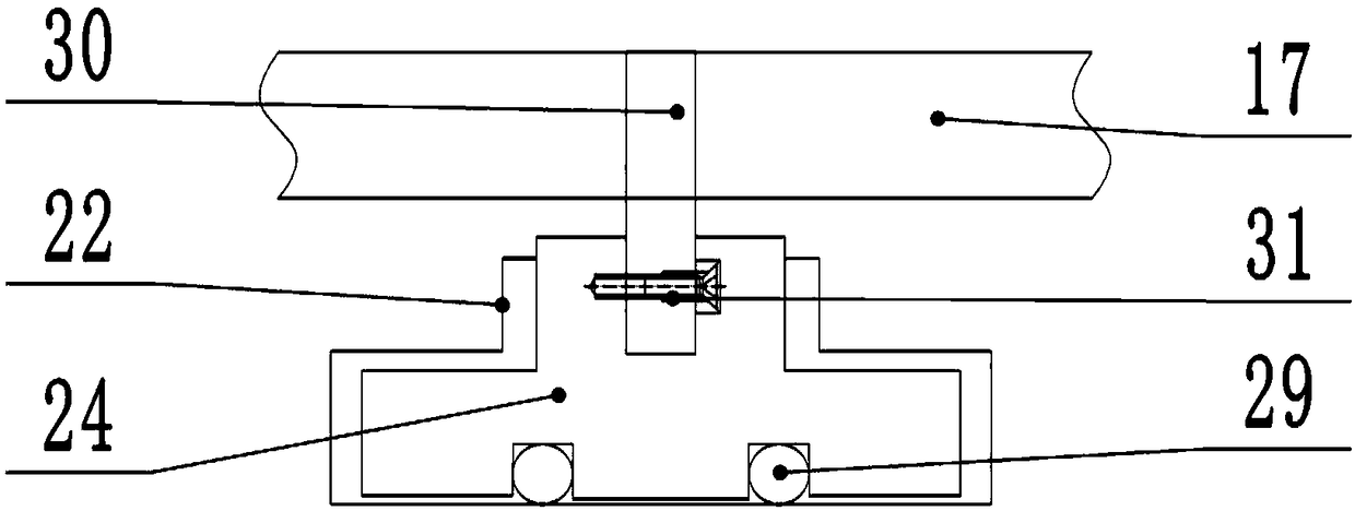
[0021] see figure 1 , a drilling buffer adjustable support for mining, including: a leg 1, a leg connecting rod 2, an upper fixed plate 10 and a drill bit 28, the leg 1 is placed in the mine and used, such as figure 2 As shown, the bottom of the support foot 1 is hollowed out in the middle, and corner brackets 19 are arranged around it, and the corner brackets 19 are structures with a large upper part and a smaller lower part to improve stability. The lower end of the corner bracket 19 is provided with a raised anti-slip block , after quenching treatment, the hardness reaches HRC=55-65, anti-slip and wear-resistant, the bottom of the support foot 1 is provided with a chassis installation hole 20, and the bolt passes through the chassis installation hole 20 to fix the support foot 1 to the lower end of the connection rod 2 of the support foot. The...


PUM


Abstract

The invention discloses a drilling buffering adjustable support for mining. The support comprises legs, leg connecting rods, an upper fixed plate and a drill bit, the middle of the bottom of each legis hollow, the periphery of the bottom of each leg is provided with a corner support, the middle of each installing plate is provided with a spring in a locking way via a fixing screw, a traversing track is fixedly mounted on a drilling platform, support bars are fixedly mounted in the upper of traversing screws via fastening screws respectively, and the support bars are installed in a motor soleplate by welding. Each corner support is of a structure which is larger in the upper and smaller in the lower, the stability is improved, the hardness reaches HRC=55-65 after quenching, the support isantiskid and wear resistance, the middle of the bottom of each leg is provided with a chassis installing hole, a level meter is fixedly mounted in the outer ring of the chassis installing hole, and the levelness is observed visually and adjusted timely; and due to design of the springs and related structure, buffering during work of the motor soleplate and drilling bit is improved, a positioning offset due to a lot of vibration during processing is avoided, and further precision deviation is avoided.

Description

technical field [0001] The invention relates to the field of mining, in particular to a drilling buffer adjustable support for mining. Background technique [0002] Mining machinery is the mechanical equipment used for direct mining of useful minerals and mining preparations. It mainly includes mining machinery for mining metal ore and non-metallic ore; coal mining machinery for mining coal; oil drilling machinery for oil mining. Drilling machines are divided into rock drills and drilling rigs, and drilling rigs are divided into surface drilling rigs and downhole drilling rigs. A rock drill is a machine used to drill holes with a diameter of 20-100 mm and a depth of less than 20 meters in rocks above medium hardness. According to its power, it can be divided into pneumatic, internal combustion, hydraulic and electric rock drills. Dynamic rock drills are the most widely used; surface drilling rigs are divided into steel rope percussion drilling rigs, down-the-hole drilling r...

Claims


Application Information

Patent Timeline
Patent Type & Authority Applications(China)
IPC IPC(8): E21B15/00
CPCE21B15/003
Inventor 徐志华
Owner 徐志华
Learn More