Sand box molding line and working method thereof

A sand box molding and sand box technology, which is applied in the direction of manufacturing tools, casting molding equipment, casting workshops, etc., can solve problems such as unreasonable layout, poor process environment, and long production cycle, so as to save the crane transfer process, The effect of shortening the production cycle and improving production efficiency

Active Publication Date: 2019-01-18
KOCEL INTELLIGENT FOUNDRY IND INNOVATION CENT CO LTD
View PDF7 Cites 5 Cited by
  • Summary
  • Abstract
  • Description
  • Claims
  • Application Information

AI Technical Summary

Problems solved by technology

[0003] The invention overcomes the problems in the prior art such as poor sand box molding process environment, heavy physica

Method used


Image

  • Sand box molding line and working method thereof
  • Sand box molding line and working method thereof

Examples


Example Embodiment

[0026] Example one:

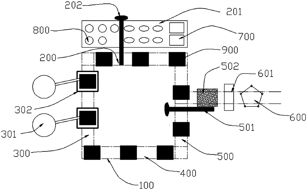
[0027] A sand box molding line, such as figure 2 Shown includes: self-flowing double-speed conveyor line 100, box buckling station 200, sand filling and tapping station 300, hardening station 400, and demolding station 500.

[0028] Such as figure 2 As shown, the boxing station 200, the sand filling and tapping station 300, the hardening station 400, and the demolding station 500 are distributed counterclockwise in sequence on the four sides of the rectangle. The boxing station 200 includes a storage and Button box manipulator, the button box manipulator can cover the storage warehouse 201 and the button box station 200, the button box manipulator 202 is used to grab the mold 800 and sand box 700 to be used from the storage warehouse 201 to the mobile shape Platform 900; the sand filling and compaction station 300 includes a sanding device 301 and a vibrating compaction table 302, the sanding device 301 is used to move sand into the sand box 700, and the v...

Example Embodiment

[0038] Embodiment two:

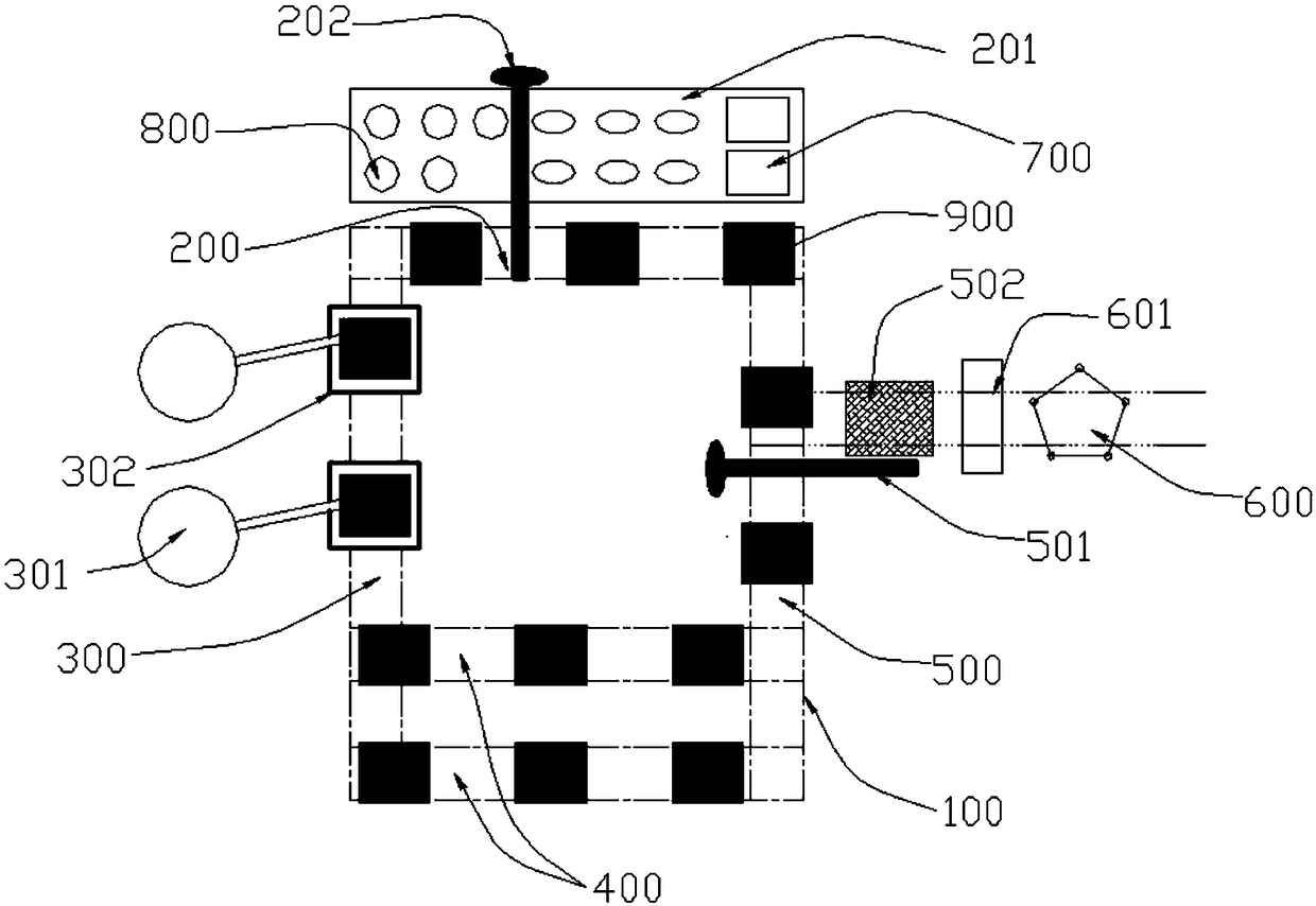
[0039] A sand box 700 molding line, such as figure 2 Shown includes: self-flowing double-speed conveyor line 100, box buckling station 200, sand filling and tapping station 300, hardening station 400, demoulding station 500 and intelligent control system;

[0040] The boxing station 200, the sand-filling and tapping station 300, the hardening station 400 and the demolding station 500 are arranged counterclockwise in sequence on the four sides of the rectangle. The boxing station 200 includes a storage 201 and a box Manipulator 202, the box manipulator 202 can cover the storage 201 and the box station 200, the box manipulator 202 is used to grab the mold 800 and sand box 700 to be used from the storage 201 to the mobile shape Platform 900; the sand filling and compaction station 300 includes a sanding device 301 and a vibrating compaction table 302, the sanding device 301 is used to move sand into the sand box 700, and the vibrating compaction table 302 is...


PUM


Abstract

The invention relates to a sand box molding line. The sand box molding line comprises a free-running multi-rate conveying line, a box locking workstation, a filling sand compaction workstation, a hardening workstation and a demolding workstation; the box locking workstation, the filling sand compaction workstation, the hardening workstation and the demolding workstation are connected in sequence to form a rectangular sand box molding line by virtue of the free-running multi-rate conveying line; the box locking workstation comprises a storage library and a box locking manipulator; the filling sand compaction workstation comprises a sand feeding apparatus and a vibration compaction table; the hardening workstation is used for hardening a sand mold in the sand box; and the demolding workstation is provided with a box overturning manipulator and a fixing mechanism. According to the sand box molding line, the box locking workstation, the filling sand compaction workstation, the hardening workstation and the demolding workstation are reasonably distributed, so that the consistence in production can be ensured, the working efficiency can be improved, the use of overhead cranes can be reduced by utilizing the manipulator and an intelligent control system, the automatic warehousing is realized, the automatic transshipping is realized, the production efficiency is improved, and the laborintensity is alleviated.

Description

technical field [0001] The invention relates to a sand box molding line, in particular to a sand box molding line for sand casting and a working method thereof. Background technique [0002] In the current foundry industry, there are problems such as poor continuity between steps, more intermediate transfers, more heavy manual labor and poor operating environment when molding sand boxes. Therefore, how to realize the automation and mechanization of the molding of the sand box, and ensure that the sand box can not only meet the production rhythm in the automatic production process, but also replace the traditional manual, crane operation and storage of semi-finished products, is a difficult problem in the sand box molding process of foundry factories. Contents of the invention [0003] The invention overcomes the problems in the prior art such as poor environment of the sand box molding process, heavy physical labor, long production cycle, unreasonable layout, and long time...

Claims


Application Information

Patent Timeline
IPC IPC(8): B22C25/00
CPCB22C25/00
Inventor 袁海军袁旭鹏王绍刚田学智任悦
Owner KOCEL INTELLIGENT FOUNDRY IND INNOVATION CENT CO LTD
Why Eureka
Try Eureka