Ultrasonic vibration assisted friction welding method

A technology of ultrasonic vibration and friction welding, applied in welding equipment, non-electric welding equipment, metal processing equipment, etc., can solve the problems of poor strength of welded joints, achieve the effects of improving strength, promoting plastic deformation, and effective connection

Inactive Publication Date: 2019-01-18
NORTHWESTERN POLYTECHNICAL UNIV
View PDF10 Cites 4 Cited by
  • Summary
  • Abstract
  • Description
  • Claims
  • Application Information

AI Technical Summary

Problems solved by technology

[0006] In order to overcome the deficiency of poor strength of welded joints in the existing assisted friction welding method, the present invention provides an ultrasonic vibration assisted friction welding method

Method used


Image

  • Ultrasonic vibration assisted friction welding method
  • Ultrasonic vibration assisted friction welding method
  • Ultrasonic vibration assisted friction welding method

Examples


Embodiment 1

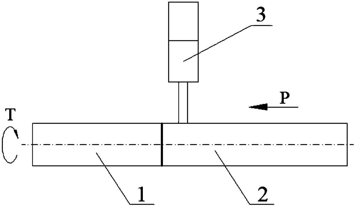
[0024] Embodiment 1: refer to figure 1 , the specific steps of the ultrasonic vibration assisted friction welding method in this embodiment are as follows:

[0025] Step 1. Clamp the workpiece 1 at the rotating end and the workpiece 2 at the moving end respectively on the rotating fixture and the moving fixture of the rotary friction welding machine;

[0026] Step 2. The rotary friction welding machine drives the workpiece 1 at the rotating end to rotate through the spindle motor and the rotating fixture. The hydraulic system at the moving end drives the workpiece 2 at the moving end to gradually approach and press against the workpiece 1 at the rotating end rotating at high speed through the slide table and the moving fixture. The pressure is 50-350MPa, the friction deformation is 1.0-3.0mm, and the friction time is 3-12s; at the same time, the output head 3 of the ultrasonic transducer is pressed on the workpiece 2 at the mobile end, and ultrasonic vibration is applied to th...

Embodiment 2

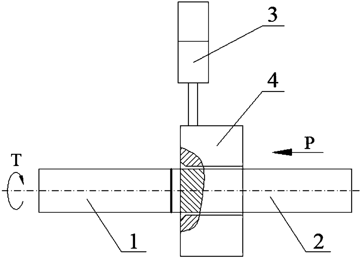
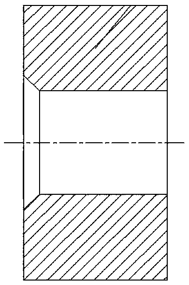
[0027] Embodiment 2: refer to Figure 2-3 , On the basis of Embodiment 1, the workpiece 2 at the mobile end is constrained, and the rest of the welding methods are the same. The specific steps of the ultrasonic vibration assisted friction welding method in this embodiment are as follows:

[0028] Step 1. Clamp the workpiece 1 at the rotating end and the workpiece 2 at the moving end respectively on the rotating fixture and the moving fixture of the rotary friction welding machine, and put the restraint sleeve 4 on the workpiece 2 at the moving end. The restraint sleeve 4 and the workpiece 2 at the moving end The gap is 0.2 ~ 0.5mm, and the workpiece 2 on the mobile end to be welded extends out of the restraint sleeve 4 by 4.0 ~ 4.2mm;

[0029] Step 2. The rotary friction welding machine drives the workpiece 1 at the rotating end to rotate through the spindle motor and the rotating fixture. The hydraulic system at the moving end drives the workpiece 2 at the moving end to grad...

Embodiment 3

[0030] Embodiment 3: refer to Figure 4 , On the basis of Example 1, the rotary friction welding machine is replaced by a linear friction welding machine, and the rotating fixture is replaced by a vibrating fixture. The specific steps of the ultrasonic vibration assisted friction welding method in this embodiment are as follows:

[0031] Step 1. Clamp the vibrating end workpiece 5 and the moving end workpiece 2 on the vibrating fixture and the moving fixture of the linear friction welding machine respectively;

[0032] Step 2. The linear friction welding machine drives the vibration end workpiece 5 to reciprocate up and down with high frequency and small amplitude through the hydraulic system of the vibration end and the vibration fixture. The vibration frequency is 20-60Hz and the amplitude is 1-3mm; The moving fixture drives the moving workpiece 2 to gradually approach and press against the reciprocating vibrating workpiece 5, the friction pressure is 50-350MPa, the frictio...


PUM


Abstract

The invention discloses an ultrasonic vibration auxiliary friction welding method, which is used for solving the technical problem of poor strength of a welding joint of the existing auxiliary friction welding method. The technical scheme is that in the process of rotating or linear friction welding, in addition to applying positive pressure and friction shearing force on the friction interface togenerate friction heat and plastic deformation, ultrasonic vibration is applied on the workpiece at the moving end, and the ultrasonic vibration transmitted to the friction interface can reduce the deformation resistance of high-temperature metal on the friction interface and promote the plastic deformation thereof, so that a larger plastic deformation amount can be generated even under a smallerfriction pressure, and finally the effective connection of workpieces at two sides is realized, and the strength of the friction welding joint is improved.

Description

technical field [0001] The invention relates to an auxiliary friction welding method, in particular to an ultrasonic vibration-assisted friction welding method. Background technique [0002] Ultrasound is a sound wave with a frequency higher than 20kHz, which has the characteristics of high power, strong directionality and strong penetration. It has the functions of breaking the oxide film, breaking the continuous brittle phase, promoting the flow of metal, improving the plasticity of the material, and refining the grain of the weld, and has a wide range of applications in the field of welding. [0003] Document 1 "Chinese Invention Patent Application Publication No. CN106238901A" discloses an ultrasonic-assisted friction stir welding welding tool and welding method. In this method, the ultrasonic machining tool is fixed at the non-rotating position of the host head, and the end surface of the ultrasonic machining tool is in contact with the surface of the material to be we...

Claims


Application Information

Patent Timeline
Patent Type & Authority Applications(China)
IPC IPC(8): B23K20/12
CPCB23K20/122
Inventor 杜随更王松林李文采李志远
Owner NORTHWESTERN POLYTECHNICAL UNIV
Why Eureka
Try Eureka