Vehicle-mounted substation

A substation and vehicle-mounted technology, which is applied in the field of substations, can solve the problems of inability to pass cables smoothly and easily hang up cables in substations, and achieve the effects of excellent mechanical properties and insulation properties, light weight and strong adhesion.

Active Publication Date: 2019-01-18
国网河南省电力公司社旗县供电公司
View PDF7 Cites 0 Cited by
  • Summary
  • Abstract
  • Description
  • Claims
  • Application Information

AI Technical Summary

Problems solved by technology

However, this invention cannot smoothly pass through areas with low cabl

Method used


Image

  • Vehicle-mounted substation
  • Vehicle-mounted substation
  • Vehicle-mounted substation

Examples


Embodiment 1

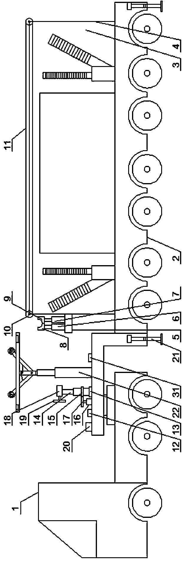
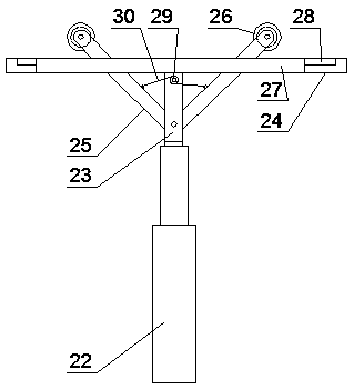
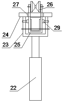
[0037] like figure 1 , figure 2 and image 3 As shown, a vehicle-mounted substation includes a tractor 1 and a trailer 2, the trailer 2 is provided with a substation body 3, the substation body 3 is covered with a protective frame 4, and the upper part of the front end of the trailer 2 is provided with a On the way, hang up the protective mechanism of the cables located above the substation body 3;

[0038] Described protective mechanism comprises the platform 5 that is arranged on the front end side of described protective frame 4, and the left automatic elevating rod 6 and the right automatic elevating rod 7 that are arranged side by side on described platform 5, are arranged on described left automatic elevating rod 6 upper ends The left top block 8 is arranged on the right top block 9 on the upper end of the right automatic lifting rod 7, and the quarter arc groove on the right side of the left top block 8 is opened on the left side of the right top block 9. The quarte...

Embodiment 2

[0050]The difference from Example 1 is that the waterproof layer contains components and their contents: 16 parts by weight of polyaniline, 2.5 parts by weight of polymethyl methacrylate, 7 parts by weight of chloroform, N,N-di 42 parts by weight of methyl formamide, 16 parts by weight of sodium silicate, 2.8 parts by weight of sodium lauryl sulfate, 8 parts by weight of nano silicon dioxide, 6 parts by weight of sodium methyl silicate, tetrachloroterephthalic acid di 3.7 parts by weight of methyl ester, 8.9 parts by weight of cinnamaldehyde, 23 parts by weight of acetone, and 48 parts by weight of deionized water.

Embodiment 3

[0052] The difference from Example 1 is that the waterproof layer contains components and their contents: 17 parts by weight of polyaniline, 3 parts by weight of polymethyl methacrylate, 7.5 parts by weight of chloroform, N,N-di 44 parts by weight of methyl formamide, 16.5 parts by weight of sodium silicate, 3 parts by weight of sodium lauryl sulfate, 9 parts by weight of nano silicon dioxide, 6.1 parts by weight of calcium stearate, dimethyl tetrachloroterephthalate 3.9 parts by weight of ester, 9 parts by weight of polyaspartic acid, 24 parts by weight of acetone, and 50 parts by weight of deionized water.


PUM

PropertyMeasurementUnit
Thicknessaaaaaaaaaa
Thicknessaaaaaaaaaa
Tensile strengthaaaaaaaaaa

Abstract

A vehicle-mounted substation includes tractors and trailers, A substation main body is arrange on that trailer, a protective frame is cover on the substation main body, a protective mechanism is arranged on the upper part of the front end of the trailer to avoid the cable hung up above the substation main body during transportation, and a binding mechanism is arranged on the trailer and on the left side of the protective mechanism to collect and bind the cable; A protection mechanism includes a platform disposed on a front side of the protective frame, The left automatic lifting lever and theright automatic lifting lever arranged side by side on the platform, the left top block arranged at the upper end of the left automatic lifting lever, the right top block arranged at the upper end ofthe right automatic lifting lever, the roller wheels arranged at the left and right ends of the top of the protective frame, and the conveyor belt sleeved on the two roller wheels. The invention has the advantages of high automation, convenience and flexibility, meanwhile, the loose cables can be tied together and the cables hung above the substation body during transportation can be avoided.

Description

technical field [0001] The invention relates to the technical field of substations, in particular to a vehicle-mounted substation. Background technique [0002] The wide application of electric energy has promoted changes in various fields of social production, ushered in the era of electric power, and the second technological revolution in modern history. Since the 20th century, the great development of the power system has made the power resources more fully developed, and the industrial layout has become more reasonable. all aspects of daily life. The development level and technical level of the power system have become one of the symbols of the economic development level of various countries. [0003] The power system consists of power plants, transmission lines, substations, and distribution networks. A substation is a power facility in the power system that transforms voltage, receives and distributes electrical energy, controls the flow of power, and adjusts voltag...

Claims


Application Information

Patent Timeline
IPC IPC(8): B60P3/00B65B13/02
CPCB60P3/00B65B13/02
Inventor 王伟石岩张性东邱国林焦玉振雷震姜军毛锋惠东军张春张爱红王丽李红阳张菲张浩
Owner 国网河南省电力公司社旗县供电公司
Why Eureka
Try Eureka