Broadband dynamic adjustable RCS reduction structure based on graphene and grating combination

A graphene and graphene layer technology, applied in diffraction gratings, antennas, electrical components, etc., can solve problems such as narrow dynamic tunable absorption bandwidth, and achieve the effect of wide regulation bandwidth

Active Publication Date: 2019-01-18
INST OF OPTICS & ELECTRONICS - CHINESE ACAD OF SCI
View PDF7 Cites 7 Cited by
  • Summary
  • Abstract
  • Description
  • Claims
  • Application Information

AI Technical Summary

Problems solved by technology

[0004] In order to solve the problem of narrow bandwidth of dynamically adjustable absorbing wave, the present invention proposes a broadband dynamically adjustable RCS reduction structure based on the combination of graphene and grating, including bottom metal layer, dielectric layer, graphene electrical control layer and high refractive index grating layer; the graphene electric control layer is composed of a high square resistance thin film layer, an insulating medium layer soaked in ionic liquid, and a PET substrate graphene layer. By combining the high refractive index grating layer and the graphene electric control Layers constitute a multi-layer RCS reduction structure, combining radiation loss and absorption loss to broaden the RCS reduction bandwidth, and only by changing the applied bias voltage of the graphene electrical control layer can realize the dynamic regulation of the RCS reduction intensity in the broadband range

Method used


Image

  • Broadband dynamic adjustable RCS reduction structure based on graphene and grating combination
  • Broadband dynamic adjustable RCS reduction structure based on graphene and grating combination
  • Broadband dynamic adjustable RCS reduction structure based on graphene and grating combination

Examples


Embodiment 1

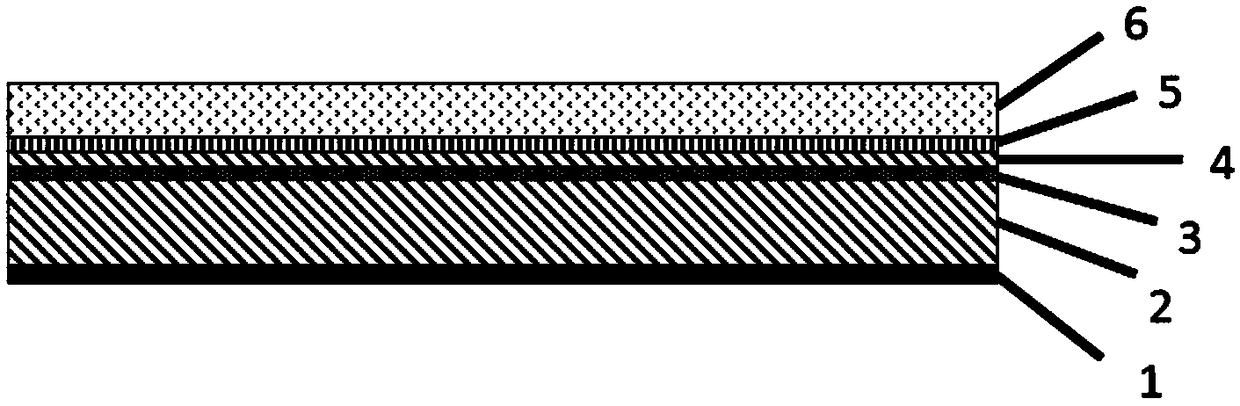
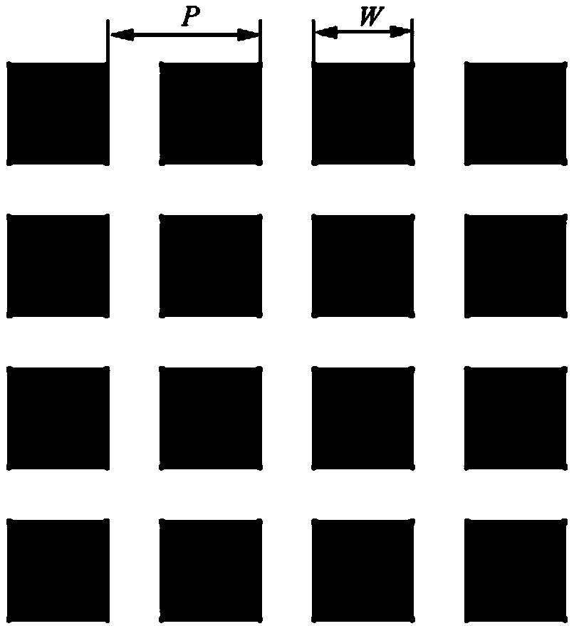
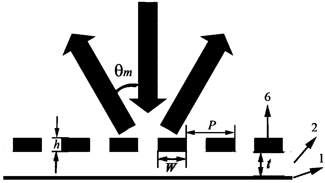
[0022] The invention designs a broadband dynamic adjustable RCS reduction structure based on the combination of graphene and high refractive index grating. Such as figure 1 As shown, the graphene-based broadband dynamically adjustable RCS reduction structure includes bottom-up: bottom metal layer 1, dielectric layer 2 (dielectric constant is ε, thickness is d), high square resistance film layer 3, wetting The ionic liquid insulating medium layer 4, the PET substrate graphene layer 5, and the high refractive index grating layer 6. The square period of the high refractive index grating layer is P=100mm, and the side length is W=65mm (such as figure 2 shown), the corresponding dielectric constant is 9.8; the dielectric layer is PMI foam, the insulating medium is a commercial Celgard PE diaphragm, and the immersion liquid is an ionic liquid which is DEMETFSI; the square resistance of the high square resistance film is 3000Ω .

[0023] Such as image 3 As shown, when the norma...


PUM

PropertyMeasurementUnit
electrical resistanceaaaaaaaaaa

Abstract

The invention provides a broadband dynamic adjustable RCS reduction structure based on graphene and grating combination. The broadband dynamic adjustable RCS reduction structure is composed of a bottom metal layer, a dielectric layer, a graphene electronic control layer and a high refractive index grating layer which are arranged in sequence from bottom to top. The graphene electronic control layer is composed of high sheet resistance film layer, an ionic liquid infiltrated insulating dielectric layer and a PET substrate graphene layer. The high refractive index grating layer and the grapheneelectronic control layer form a multilayer structure. An RCS reduction bandwidth is expanded through combination of two methods of radiation loss and absorption loss and sheet resistance of graphene is changed through adjustment of a Fermi level of the graphene based on an external bias voltage, so dynamic control over RCS reduction strength is realized in a broadband range. The broadband dynamicadjustable RCS reduction structure has the advantages that on the basis of expanding the RCS reduction bandwidth through combination of the high refractive index grating layer and the graphene electronic control layer, the RCS reduction strength can be controlled in the broadband range through utilization of the external bias voltage, and the corresponding RCS reduction strength in certain state is greater than 10dB.

Description

technical field [0001] The invention relates to the field of dynamically adjustable RCS reduction, in particular to a broadband dynamically adjustable RCS reduction structure based on the combination of graphene and gratings. Background technique [0002] In the past few decades, because of the extremely important role of radar cross-section (RCS) reduction in civilian and military fields, people have conducted extensive and in-depth research on it. So far, there are two main technical means to control the target radar scattering signal intensity: one is to directly absorb and convert incident electromagnetic waves into heat energy or other forms of energy, thereby reducing backscattered energy. Based on this principle, various absorbing structures have been designed, such as: salisbury screen absorber, jaumann absorber and frequency selective surface absorber, etc., which can directly absorb incident electromagnetic waves to achieve RCS reduction. Another RCS reduction tec...

Claims


Application Information

Patent Timeline
Patent Type & Authority Applications(China)
IPC IPC(8): G02B5/18H01Q15/00
CPCG02B5/18H01Q15/0026
Inventor 罗先刚宋甲坤黄成马晓亮蒲明博
Owner INST OF OPTICS & ELECTRONICS - CHINESE ACAD OF SCI
Why Eureka
Try Eureka