
Alignment film orientation method, alignment film substrate and display panel

An alignment film and orientation technology, applied in nonlinear optics, instruments, optics, etc., can solve the problems of residual fluff, strict light source requirements, and narrow viewing angle of liquid crystal display devices

Pending Publication Date: 2019-01-18
SOUTH UNIVERSITY OF SCIENCE AND TECHNOLOGY OF CHINA
View PDF5 Cites 0 Cited by
  • Summary
  • Abstract
  • Description
  • Claims
  • Application Information

AI Technical Summary

Problems solved by technology

Due to the birefringence of liquid crystals, the light transmittance of liquid crystal devices strongly depends on the observation method; therefore, the viewing angle of liquid crystal display devices obtained by this method is narrow
At the same time, there are still many problems in rubbing orientation: contact friction may damage the transistor on the lower side of the polymer; contact friction will leave flannel fluff, which will affect the display effect of the screen, etc.
However, in this method, the thin film material has strict requirements on the light source, and it is usually necessary to select the optical band in which the photosensitive group reacts as the light source, which poses some challenges to the flexibility of production.

Method used


Image

  • Alignment film orientation method, alignment film substrate and display panel
  • Alignment film orientation method, alignment film substrate and display panel
  • Alignment film orientation method, alignment film substrate and display panel

Examples


Embodiment 1

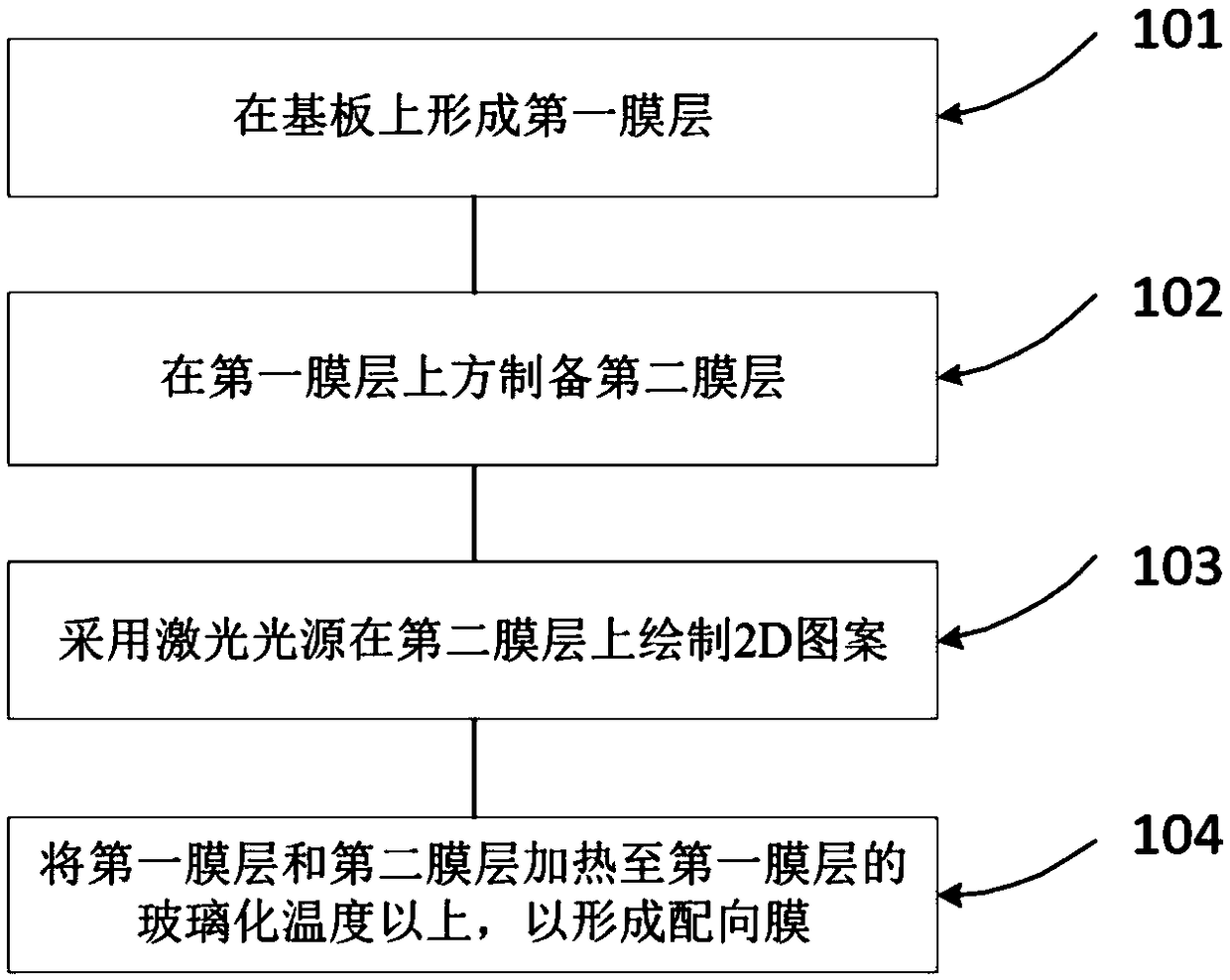
[0022] figure 1 The alignment method for the alignment film provided in Embodiment 1 of the present invention, such as figure 1 As shown, the alignment film orientation method includes the following steps:

[0023] S101, forming a first film layer on the substrate;

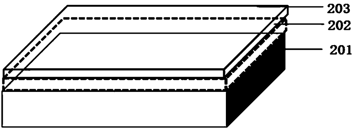
[0024] For example, the first film layer solution can be coated on the substrate, and then annealed and solidified to form the first film layer. Annealing acts to evaporate the solvent and solidify the film. The substrate can be selected from glass, silicon wafer or plastic, mainly depending on the use requirements. The plastic substrate can be bent to adapt to flexible development solutions. It should be noted that if a plastic substrate is used, the glass transition temperature of the plastic should be higher than the glass transition temperature of the first film layer, so as to avoid the vitrification change of the substrate caused by heating and affect the accumulated stress of the first film layer. The f...

Embodiment 2

[0037] An embodiment of the present invention provides an alignment film substrate, which is prepared by using the alignment film orientation method in Embodiment 1.

[0038] The alignment film substrate provided by the embodiment of the present invention adopts a double-layer film structure and is manufactured by a non-contact patterning method, which realizes any patterned orientation of liquid crystals and avoids related problems caused by contact friction. By optimizing the process parameters , can realize the fabrication of the alignment film substrate with nanoscale wrinkle period.

Embodiment 3

[0040] An embodiment of the present invention provides a display panel, which includes the alignment film substrate in the second embodiment.

[0041] Compared with the traditional display panel, the display panel in the embodiment of the present invention has a larger viewing angle, which greatly improves the user's visual experience. At the same time, the alignment film substrate of the display panel is made in a non-contact manner, which avoids the possible existence of contact friction. The problem of destroying the transistor on the lower side of the matching film substrate and remaining fluff and shavings that affect the display effect.


PUM

PropertyMeasurementUnit
Thicknessaaaaaaaaaa
Thicknessaaaaaaaaaa

Abstract

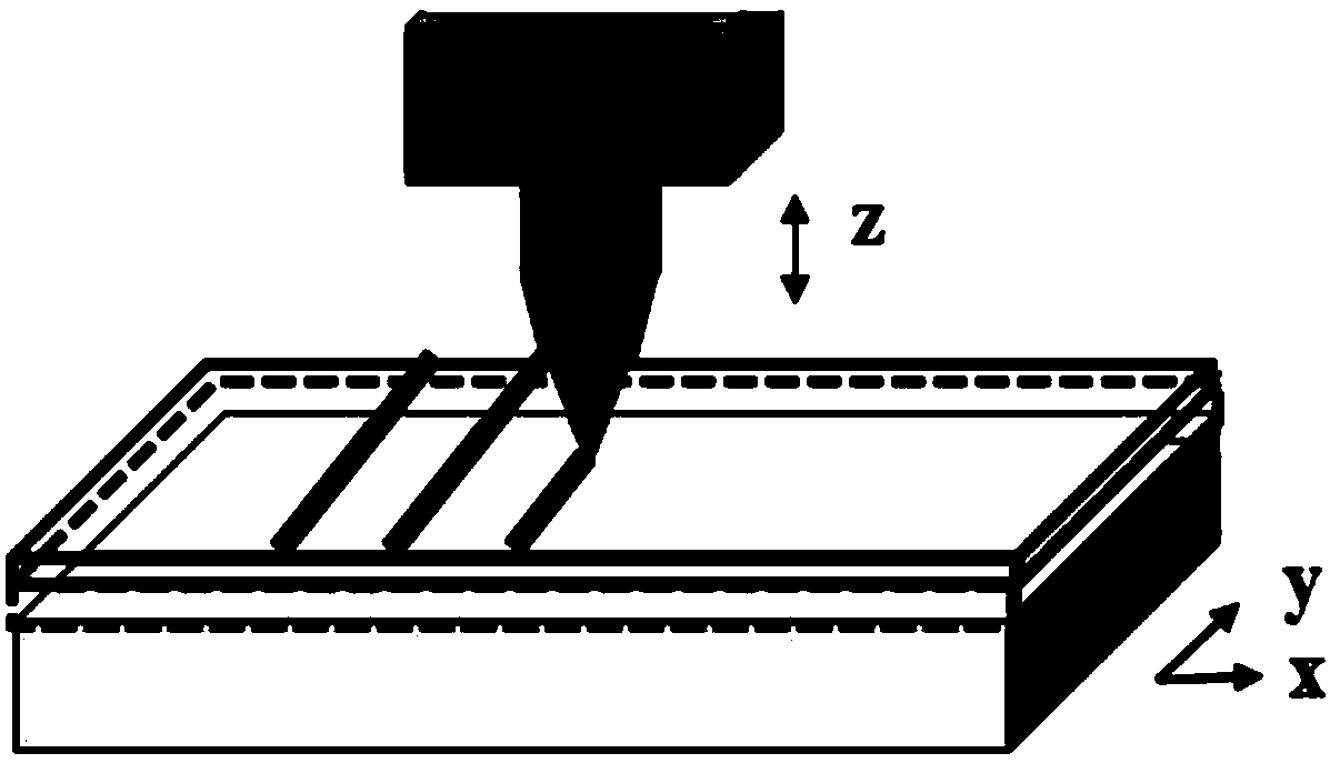
The invention discloses an alignment film orientation method comprising the steps of forming a first film layer on a substrate; preparing a second film layer on the first film layer; drawing a 2D pattern on the second film layer by using a laser light source; and heating the first film layer and the second film layer to above the glass transition temperature of the first film layer, so as to forman alignment film, wherein the Young modulus of the first film layer is less than that of the second film layer. According to the method, substrate and panel provided by the embodiment of the invention, the 2D pattern is directly written by using laser to guide a heating expansion path of the film, so as to prepare and guide liquid crystal to achieve a liquid crystal orientation plate with any patterned orientation. The method solves a series of problems caused by small visual angle and friction of a traditional mechanical friction orientation method; compared with the existing visualized liquid crystal orientation method in a scientific research stage, the method provided by the invention is applicable to large-scale production and low in cost.

Description

technical field [0001] Embodiments of the present invention relate to liquid crystal alignment technology, and in particular to an alignment film alignment method, an alignment film substrate, and a display panel. Background technique [0002] With the rapid development of the scientific and technological information industry, visualization has gradually become the common demand of various industries. At present, more than 90% of the display devices on the market use LCD screens. However, there is a relatively big problem with the LCD screen that the viewing angle is small, that is, the picture is blurred at an oblique viewing angle, and even the image cannot be recognized, which seriously affects the visual experience of consumers. [0003] This is because the liquid crystal alignment method currently used in the display industry chain is mainly the mechanical rubbing alignment method. This method is mainly by wrapping the flannelette outside the roller, rolling the roller...

Claims


Application Information

Patent Timeline
IPC IPC(8): G02F1/1337
CPCG02F1/133788
Inventor 刘言军李珂张建明张一帆
Owner SOUTH UNIVERSITY OF SCIENCE AND TECHNOLOGY OF CHINA
Learn More