Respiratory bottle for measuring respiratory rate of biofilm, measuring device and measuring method

A technology of respiration rate and biofilm, applied in the field of measuring device and respiration bottle for measuring the respiration rate of biofilm, can solve the problems of interfering with magnetic stirrer, changing mass transfer rate, affecting oxygen mass transfer, etc., to achieve accurate and real growth conditions, The measurement results are accurate and effective, and the effect of avoiding irreversible damage

Active Publication Date: 2019-01-25
JINAN UNIVERSITY
View PDF6 Cites 3 Cited by
  • Summary
  • Abstract
  • Description
  • Claims
  • Application Information

AI Technical Summary

Problems solved by technology

One is to directly put the filler into the breathing bottle, and match it with magnetic stirring, so as to conduct a breath dynamics test; during the test, the filler will interfere with the rotation of the magnetic stirrer and affect the oxygen mass transfer; in addition, the magnetic stirrer will put the filler on the The biofilm is scraped off, thereby destroying the biofilm structure and affecting the measurement results; in fact, the measurement cannot be realized
The other is to directly centrifuge the MBBR filler to make the biofilm on the filler fall off, suspend it in water, and then carry out the respiratory dynamics experiment according to the conventional method; this method has caused irreversible damage to the biofilm on the filler; At the same time, the shedding of the biofilm leads to changes in the mass transfer rate of oxygen on the surface of the filler biofilm, which cannot truly reflect the respiratory dynamics of the biofilm.

Method used


Image

  • Respiratory bottle for measuring respiratory rate of biofilm, measuring device and measuring method
  • Respiratory bottle for measuring respiratory rate of biofilm, measuring device and measuring method
  • Respiratory bottle for measuring respiratory rate of biofilm, measuring device and measuring method

Examples


Embodiment 1

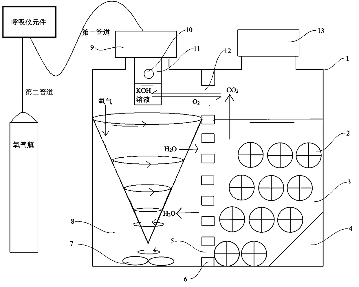
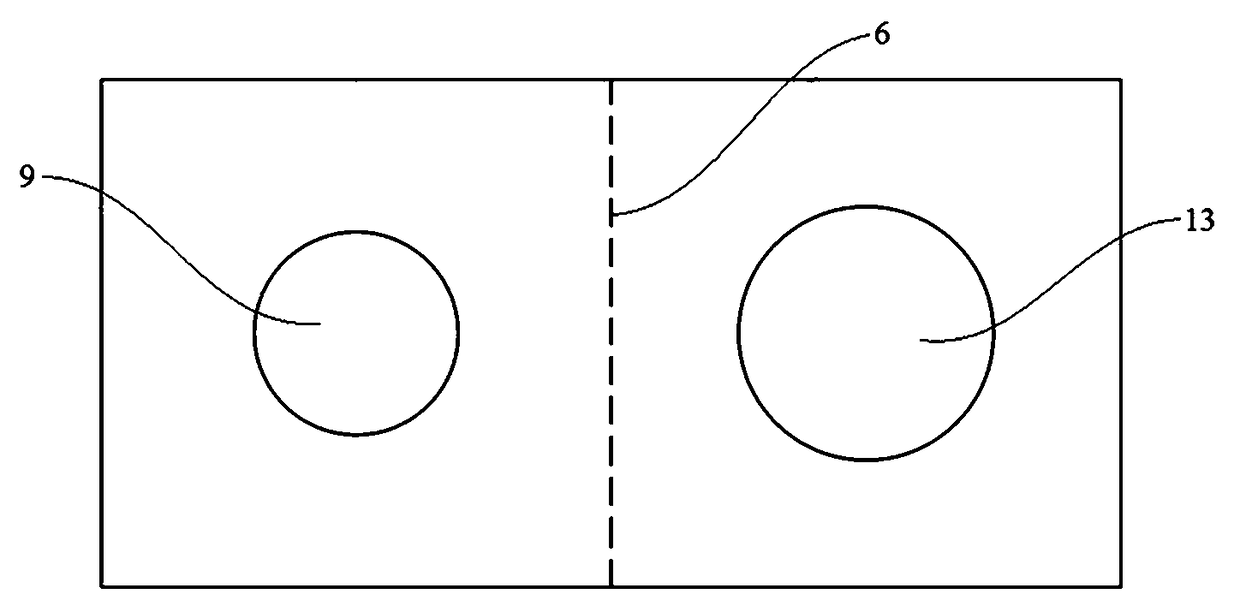
[0037] figure 1 It is the schematic diagram of the respirator composition measuring device that is connected to the breather bottle for measuring the oxygen absorption rate of the embodiment 1 for measuring the biofilm respiration rate, figure 2 It is the top view of the breathing bottle of embodiment 1. Such as Figure 1-2 Shown, a kind of breathing bottle that is used for measuring biofilm respiration rate of the present invention comprises bottle body 1, carbon dioxide absorption tube 11 and the perforated partition 6 that is arranged on bottle body 1 inside; Divided into an oxygen mass transfer stirring zone 8 and a biofilm reaction zone 3, the oxygen mass transfer stirring zone 8 is provided with a stirring device 7, and the biofilm reaction zone 3 is used to place MBBR filler 2; the carbon dioxide absorption pipe 11 is provided with a vent hole 10 and contains Capable of absorbing CO 2 KOH solution to absorb CO in bottle 1 2 The perforated partition 6 has a first ho...

Embodiment 2

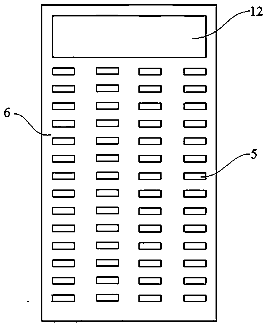
[0047] Figure 4 The schematic diagram of the respirator composition measuring device for measuring the oxygen absorption rate connected to the breathing bottle for measuring the biofilm respiration rate of embodiment 2 and embodiment 3, Figure 5 It is the top view of the breathing bottle of embodiment 2. This embodiment is the second embodiment of the breathing bottle of the present invention, as Figure 4-5 As shown, the difference from Example 1 is: the bottle body 1 in this embodiment is a cylinder; the perforated partition 6 is cylindrical, and the inside of the cylindrical perforated partition 6 is an oxygen mass transfer stirring zone 8, and the cylinder Between the outside of the shaped perforated partition 6 and the bottle body 1 is the biofilm reaction zone 3; the perforated partition 6 is located in the middle of the bottle body 1, and the first bottleneck corresponds to the oxygen mass transfer stirring zone inside the cylindrical perforated partition 8. The bot...

Embodiment 3

[0050] Figure 4 The schematic diagram of the respirator composition measuring device for measuring the oxygen absorption rate connected to the breathing bottle for measuring the biofilm respiration rate of embodiment 2 and embodiment 3, Image 6 It is the top view of the breathing bottle of embodiment 3. This embodiment is the second embodiment of the breathing bottle of the present invention, as Figure 4 with Image 6 As shown, the difference from Example 1 is that there are two perforated partitions 6, an oxygen mass transfer stirring zone 8 between the two perforated partitions 6, and a biofilm between the perforated partition 6 and the bottle body 1. Reaction zone 3; bottle body 1 is provided with two second bottlenecks, and described two second bottlenecks correspond to two biofilm reaction zones 3 respectively; Described two second bottlenecks are respectively provided with the seal that is used for sealing bottle cap13.

[0051] The CO released by the microbial re...


PUM


Abstract

The invention discloses a breathing bottle for measuring the breathing rate of a biofilm, comprising a bottle body, a carbon dioxide absorbing tube and a perforated separator arranged inside the bottle body; a perforated partition plate divides the inside of the bottle body into an oxygen mass transfer stirring zone provided with a stirring device and a biofilm reaction zone used for placing MBBRfillers; the carbon dioxide absorbing tube is provided with a permeable hole and contains a solution capable of absorbing CO<2>; a perforated separator has a first hole corresponding to a middle portion and a lower portion of the perforated separator and serving as a liquid exchange channel and a second hole corresponding to an upper portion of the perforated separator and serving as a gas exchange channel, and the oxygen transfer stirring zone is communicated with the biofilm reaction zone through the liquid exchange channel and the gas exchange channel. On the one hand, the fact that gas-liquid exchange of the oxygen transfer stirring zone and the biofilm reaction zone is fully processed is ensured. On the other hand, the stirring device can avoid the destruction of biofilm on MBBR packing, so the respiratory kinetic characteristics of biofilm on MBBR packing can be measured in situ. The determination process is simpler, quicker, and the determination results are more accurate and effective.

Description

technical field [0001] The invention relates to the field of sewage treatment, in particular to a breathing bottle, a measuring device and a measuring method for measuring the respiration rate of a biofilm. Background technique [0002] Fluidized bed biofilm reactor (MBBR) is a new type of biofilm reactor, which is an improved new composite biofilm developed on the basis of fixed bed reactor, fluidized bed reactor and biofilter. reactor. The process requires the use of suspended fillers to provide a suitable growth environment for microorganisms. Determining the respiratory dynamics characteristics of biofilm on MBBR suspended packing is extremely important for optimizing the design and operation of sewage treatment process. [0003] There are two existing methods for measuring the respiration dynamics of biofilms on MBBR fillers. One is to directly put the filler into the breathing bottle, and match it with magnetic stirring, so as to conduct a breath dynamics test; duri...

Claims


Application Information

Patent Timeline
Patent Type & Authority Applications(China)
IPC IPC(8): C12M1/34C12M1/24C12M1/04C12M1/02C12M1/00C12Q1/02
CPCC12M23/08C12M23/34C12M23/38C12M25/02C12M27/04C12M29/04C12M41/46C12Q1/02C12Q2304/44Y02W10/10C12M25/18C12M25/20C12M41/34C12M41/48C02F2209/36C02F3/085C12M29/20
Inventor 刘国强卢子川
Owner JINAN UNIVERSITY
Why Eureka
Try Eureka