structure of an adjustable color LED luminescence module based on fluorescent powder luminescence
A light-emitting module and fluorescent powder technology, applied in the field of lighting, can solve the problems of single innovation, easy falling off, deformation, etc., and achieve the effects of simplifying the production process steps, improving the stability of light emission, and ensuring the efficiency of heat dissipation
- Summary
- Abstract
- Description
- Claims
- Application Information
AI Technical Summary
Problems solved by technology
Method used
Image

Examples
Embodiment 1
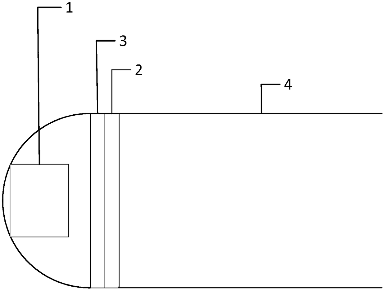
[0026] Embodiment 1 of the present invention such as Figure 1-3 The structure of a tunable color LED light-emitting module based on fluorescent powder light-emitting is shown, including a light-emitting chip 1, a phosphor powder coating layer 2, and a liquid crystal driving layer 3. The light-emitting chip 1, liquid crystal driving layer 3 and fluorescent The powder coating layer 2 is arranged in sequence, and the liquid crystal driving layer 3 separates the phosphor coating layer 2 from the light-emitting chip 1. The liquid crystal driving layer 3 and the phosphor coating layer 2 have the same shape and are aligned and attached to each other. The phosphor coating layer 2 is separated from the light-emitting chip 1 by the liquid crystal driving layer 3, and is bonded with the phosphor coating layer 2 for packaging, which supports the phosphor layer and ensures the heat dissipation efficiency of the light-emitting chip 1. On the basis of the above, the stability of the phospho...
Embodiment 2
[0031] This embodiment is basically the same as Embodiment 1, the difference is:
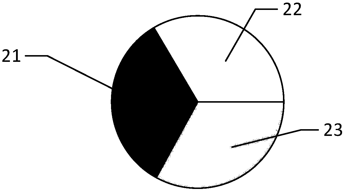
[0032]The phosphor coating layer 2 includes a first groove 21, a second groove 22 and a third groove 23, and the first groove 21, the second groove 22 and the third groove 23 are respectively coated with red Phosphor, Green Phosphor, and Blue Phosphor.
[0033] Further, the first groove 21 , the second groove 22 and the third groove 23 are engraved with corresponding groove shapes by photolithography technology, and corresponding phosphor powder is coated on them.
[0034] Preferably, the phosphor coating layer 2 is made of a transparent material with high light transmittance
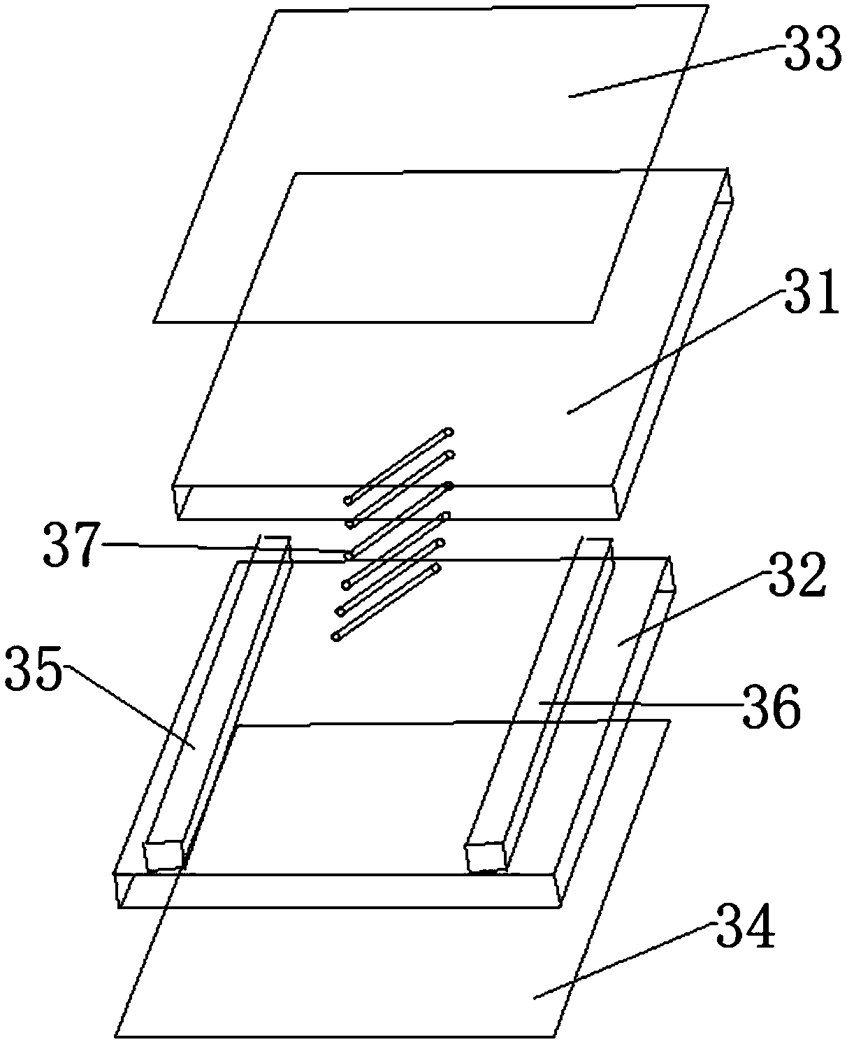
[0035] Further, the liquid crystal layer 37 includes a first liquid crystal region, a second liquid crystal region and a third liquid crystal region, and the first liquid crystal region, the second liquid crystal region and the third liquid crystal region are respectively connected to the first groove 21, The second gro...
Embodiment 3
[0038] This embodiment is basically the same as Embodiment 2, the difference is:
[0039] It also includes a reflector 4, and the light-emitting direction of the light-emitting chip 1 and / or the phosphor powder coating layer 2 faces the reflector 4, so that the light excited by the light-emitting chip 1 and the phosphor powder coating layer 2 passes through the The reflector 4 is reflected and emitted. The light emitted by the light-emitting chip 1 is reflected by the reflector 4 and emitted concentratedly, which can improve the conversion rate of the light source, and make the vertical light emission angle of the reflector 4 more concentrated, and the optical consistency is highly uniform.
[0040] The light-emitting chip 1 is an LED chip capable of emitting high-energy photons
[0041] Preferably, the light-emitting chip 1 is an ultraviolet LED chip.
[0042] The present invention provides a signal indicator light, including a housing, and the structure of an adjustable co...
PUM
 Abstract
Description
Claims
Application Information
 - R&D
- Intellectual Property
- Life Sciences
- Materials
- Tech Scout
- Unparalleled Data Quality
- Higher Quality Content
- 60% Fewer Hallucinations
Browse by: Latest US Patents, China's latest patents, Technical Efficacy Thesaurus, Application Domain, Technology Topic, Popular Technical Reports.
© 2025 PatSnap. All rights reserved.Legal|Privacy policy|Modern Slavery Act Transparency Statement|Sitemap|About US| Contact US: help@patsnap.com