
Electron shift type electric field intensity sensor

A technology of electric field strength and sensors, applied in the fields of electromagnetic field characteristics, electrostatic field measurement, instruments, etc., can solve problems such as poor product consistency, poor environmental adaptability, and low resolution, and achieve small electric field energy loss, good applicability, and high resolution high effect

Pending Publication Date: 2019-02-01
DALI UNIV
View PDF0 Cites 1 Cited by
  • Summary
  • Abstract
  • Description
  • Claims
  • Application Information

AI Technical Summary

Problems solved by technology

The disadvantage of this electric field sensor is that it has rotating parts, so the environmental adaptability is poor, and the product consistency of mass production is poor
[0005] The field mill type electric field sensor developed or improved by many domestic institutions, its basic principle is to use the method of periodic shielding and exposure of the conductor, so that the induced charge migration inside the conductor placed in the electric field forms an alternating current, the sensor has The metal stator and the metal rotor, the rotor is grounded through the carbon brush, and the stator is periodically shielded, so that an alternating induction current is induced on the stator, and the induction signal becomes a sinusoidal signal whose amplitude is proportional to the electric field strength through the conversion circuit. The disadvantage of this kind of electric field sensor is that it is bulky, the resolution is not high, and the environmental adaptability is poor.

Method used


Image

  • Electron shift type electric field intensity sensor
  • Electron shift type electric field intensity sensor
  • Electron shift type electric field intensity sensor

Examples


Embodiment 1

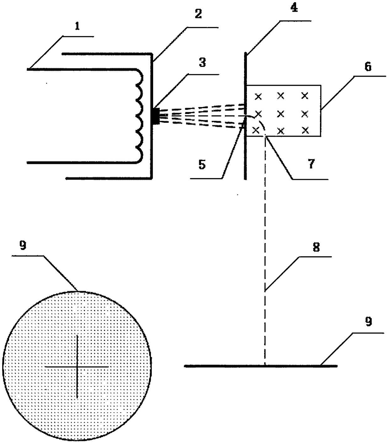
[0021] Example 1: figure 1 It is an implementation form of electronic offset electric field strength sensor. As shown in the figure, this embodiment is mainly composed of heating electrode, emitting cathode, accelerating electric field cathode, accelerating electric field anode, accelerating electric field anode small hole, screening magnetic field generating device, speed Screening pinholes, composed of charge-coupled devices. The emitting cathode emits electrons after being heated, and the electrons move forward under the action of the accelerating electric field. The accelerating electric field makes the electrons emitted by the cathode have a greater forward speed in all directions, and most of the electrons fly to the anode. Among the electrons going to the anode of the electric field, some electrons pass through the anode hole on the anode plate and enter the screening magnetic field. The screening magnetic field is a uniform magnetic field. Under the action of the magne...

Embodiment 2

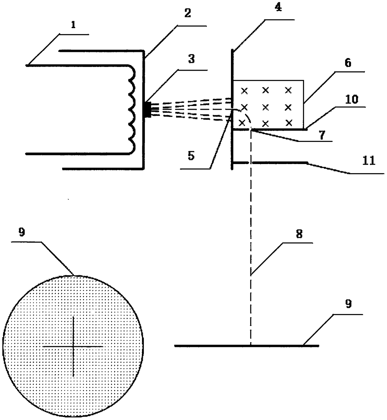
[0023] Embodiment 2: On the basis of Embodiment 1, a decelerating electric field is added after the magnetic field is screened, which becomes the second embodiment of the present invention. Such as figure 2As shown, this embodiment is mainly composed of a heating electrode, an emitting cathode, an accelerating electric field cathode, an accelerating electric field anode, an accelerating electric field anode aperture, a screening magnetic field generating device, a velocity screening aperture, a decelerating electric field and a charge coupled device. The emitting cathode emits electrons after being heated, and the electrons move forward under the action of the accelerating electric field. The accelerating electric field makes the electrons emitted by the cathode have a greater forward speed in all directions, and most of the electrons fly to the anode. Among the electrons going to the anode of the electric field, some electrons pass through the anode hole on the anode plate a...

Embodiment 3

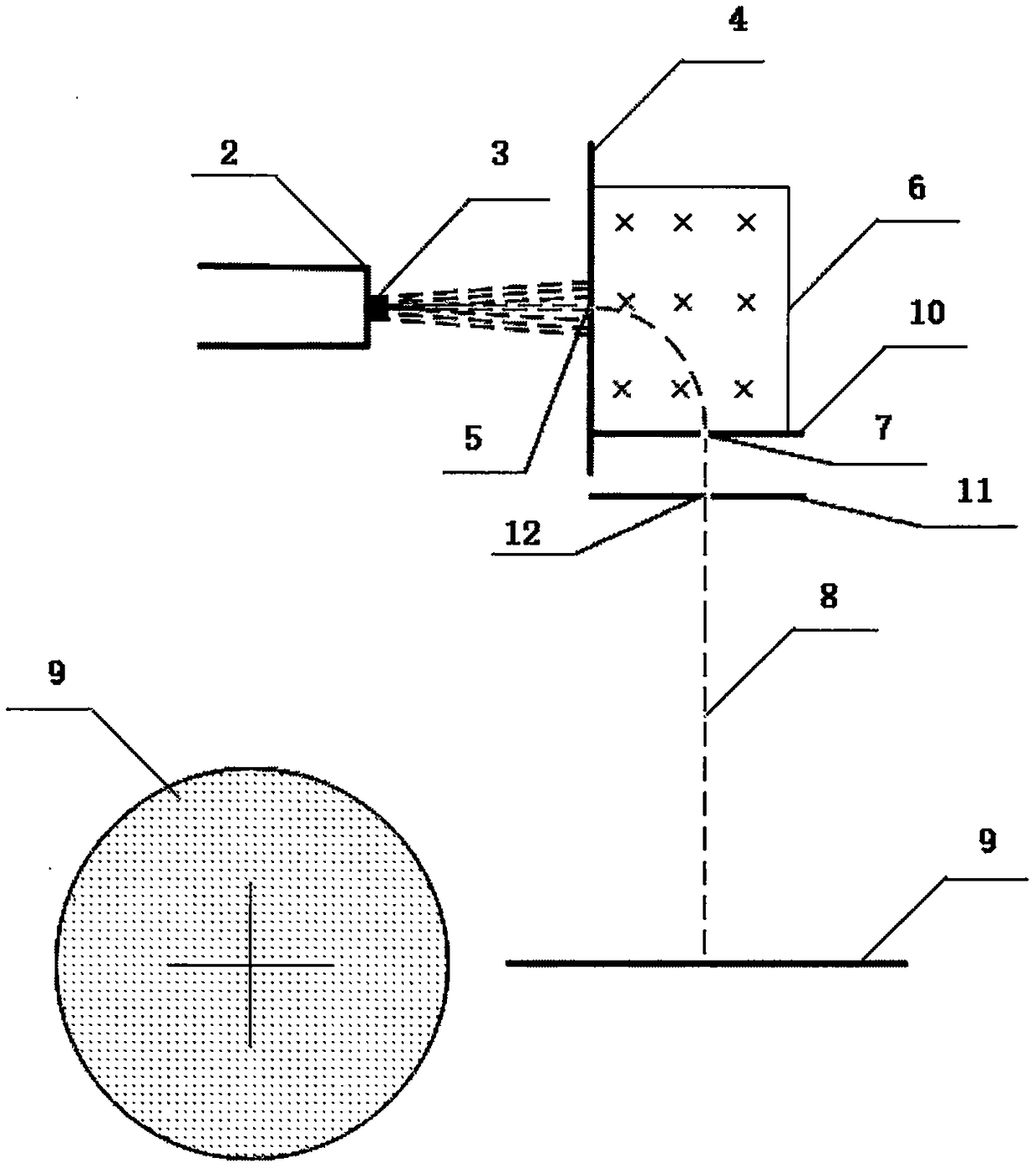
[0025] Embodiment 3: On the basis of Embodiment 2, after canceling the cathode heating device, field electron emission is used, which becomes the third embodiment of the present invention. like image 3 As shown, this embodiment is mainly made up of emitting cathode, accelerating electric field cathode (also serving as emission control grid), accelerating electric field anode, accelerating electric field anode aperture, screening magnetic field generating device, speed screening aperture, decelerating electric field and charge-coupled device . Apply a high voltage to the accelerating electric field, and the emitting cathode emits electrons under the action of the high voltage, and the electrons move forward under the action of the accelerating electric field. The high-voltage accelerating electric field makes the electrons emitted from the cathode in all directions have a great forward direction Speed, most of the electrons fly to the anode. Among the electrons flying to the ...


PUM


Abstract

The invention discloses an electron shift type electric field intensity sensor based on the principle that electron beam shifts in electric field under vacuum environment, and belongs to the technicalfield of electric field measurement. The sensor mainly comprises an electron gun assembly, an accelerating electric field, a speed screening magnetic field generation device, screening holes, a decelerating electric field assembly, a charge coupling device, an electric field shielding cover, and a magnetic field shielding cover. According to the electron shift type electric field intensity sensor, the electric field sensor is less affected by body potential, and is suitable for measuring electrostatic field, DC electric field, and low frequency AC electric field; the miniaturization of the sensor product can be realized; the measurement resolution and the result accuracy is high; one set of the device can realize two-dimensional measurement of the electric field; two sets of the same devices placed vertically can realize three-dimensional measurement of the electric field, wherein the second set of the device can share parts of components of the first set of the device; and the electric field sensor can be used to measure two-dimensional or three-dimensional electric field intensity, and can also be used to measure two-dimensional or three-dimensional magnetic field intensity.

Description

technical field [0001] The invention belongs to the technical field of electric field measurement, in particular to an electronic offset electric field intensity sensor. Background technique [0002] Measuring electric field strength is of great significance in modern life, production and scientific research. For example, in the field of power transmission, electric field measurement near power transmission lines and power transformation equipment can obtain relevant information such as voltage and current in lines and equipment; in the field of military industry, targets can be detected by measuring electric field strength; in the field of industry, electromagnetic compatibility Safety is becoming one of the key considerations in the product design process; in the field of safety production, in areas prone to fire and explosion, such as gas stations, oil refineries and flour mills, monitoring the electric field can avoid damage caused by excessive electric field strength. ...

Claims


Application Information

Patent Timeline
IPC IPC(8): G01R29/12G01R29/08G01R33/02
CPCG01R29/0878G01R29/12G01R33/02
Inventor 赵春平李志华吕建勋
Owner DALI UNIV
Learn More