
Powder recovery workbench used for metal 3D printing molding

A 3D printing and workbench technology, which is applied in the direction of additive processing, process efficiency improvement, and energy efficiency improvement, can solve problems such as waste, high labor intensity, and numerous processes, and achieve improved recycling rate, high recycling efficiency, The effect of low labor intensity

Pending Publication Date: 2019-02-05
山东泰利先进制造研究院有限公司
View PDF0 Cites 14 Cited by
  • Summary
  • Abstract
  • Description
  • Claims
  • Application Information

AI Technical Summary

Problems solved by technology

Coaxial powder feeding or side-axis powder feeding is the main form of laser cladding or laser 3D printing at present. However, the alloy powder or metal powder is not completely melted to form a cladding layer, and some of it will fall directly on the workbench. At present, The utilization rate of alloy powder formed by laser cladding or laser 3D printing is only 40% to 60%, and half of the powder is directly wasted; However, the recovered powder needs to be dried, screened and other processes. There are many processes, and most of the processes are manual operations. The labor intensity is high and the efficiency is low.
In order to solve the above problems, it is urgent to invent a powder recycling table for metal 3D printing to solve the current problem of alloy powder recycling in laser cladding molding

Method used


Image

  • Powder recovery workbench used for metal 3D printing molding
  • Powder recovery workbench used for metal 3D printing molding
  • Powder recovery workbench used for metal 3D printing molding

Examples


Embodiment Construction

[0032] The principles and features of the present invention will be described below in conjunction with examples. The examples cited are only used to explain the present invention and are not used to limit the scope of the present invention.

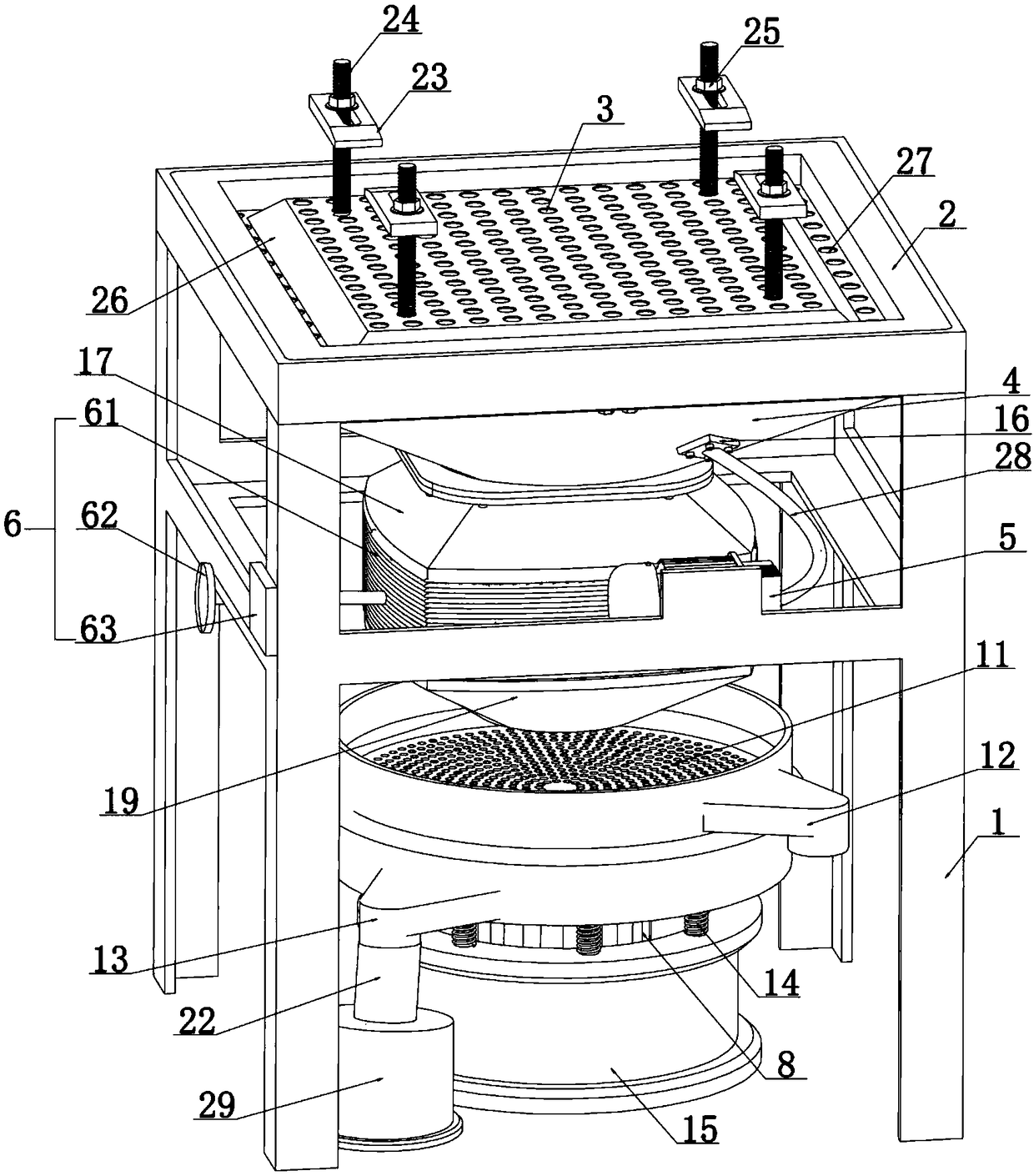
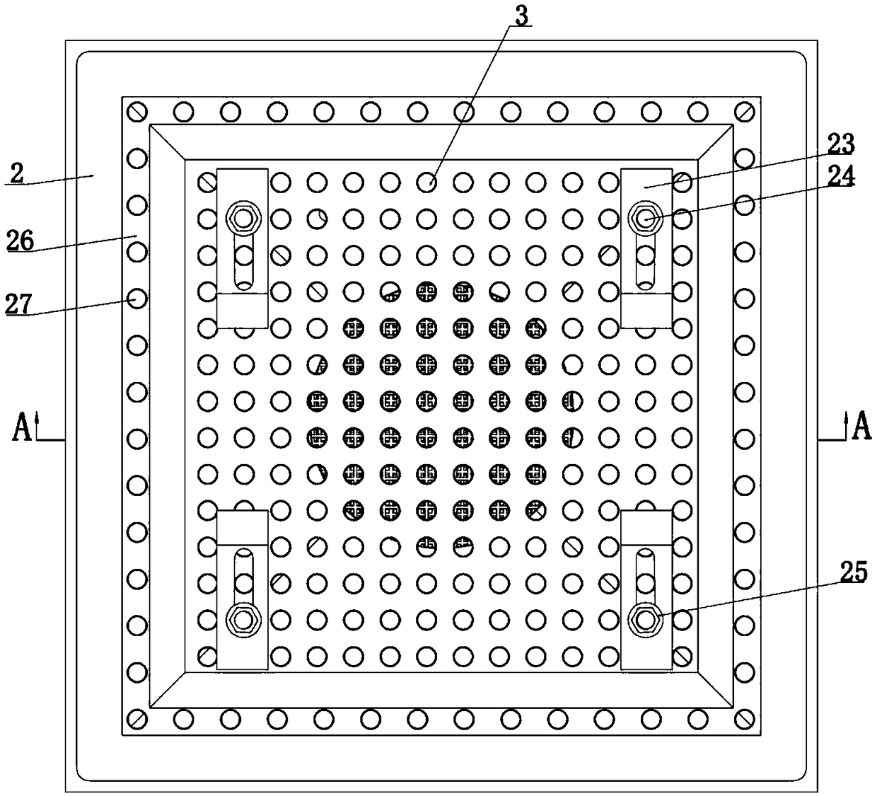
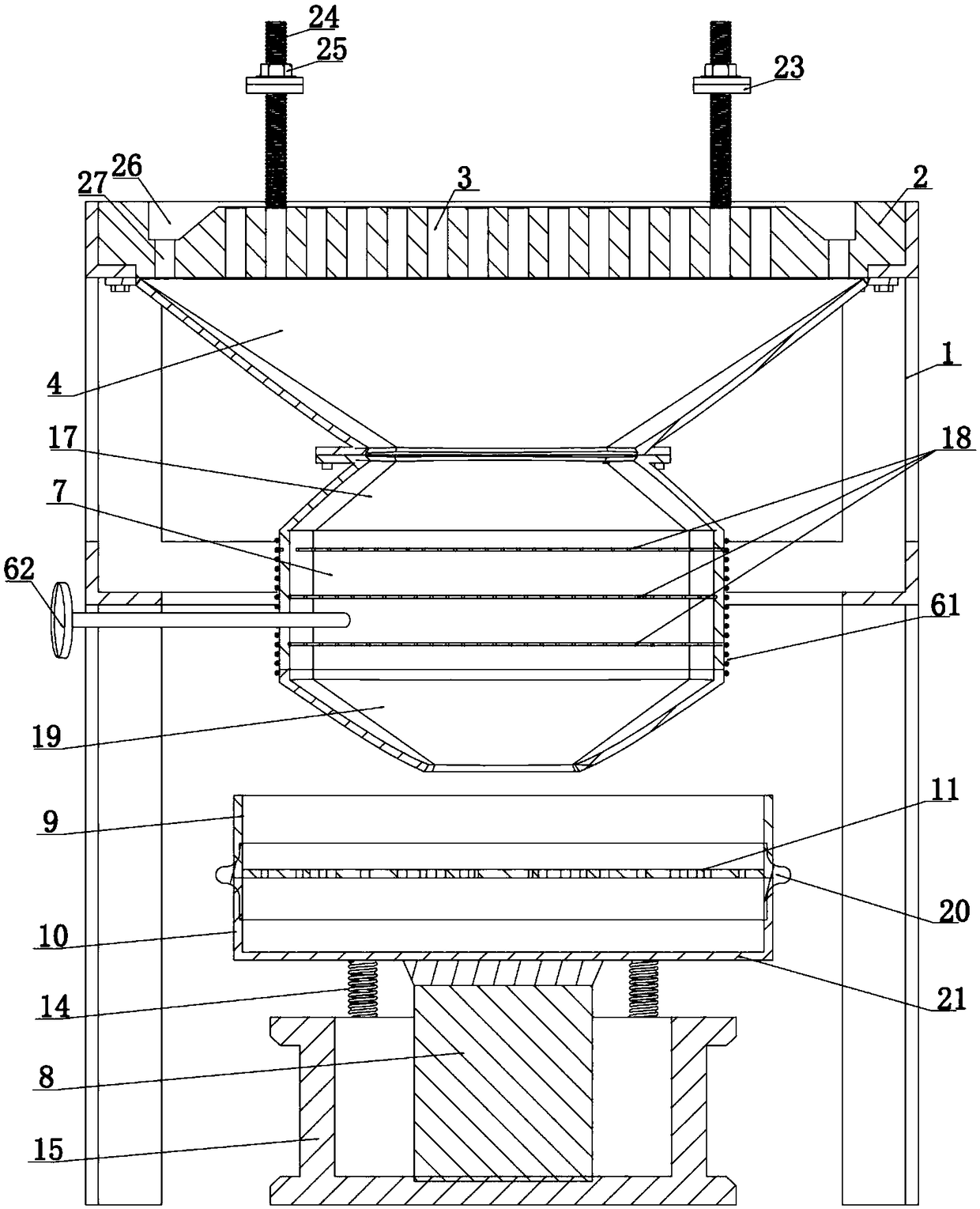
[0033] Such as Figure 1-Figure 5 As shown, a powder recovery workbench for metal 3D printing and forming includes a workbench panel 2, a powder recovery mechanism, a powder drying mechanism, a powder sieving mechanism, and a powder recovery bin 29 sequentially arranged from top to bottom. The workbench panel is arranged above the powder recovery mechanism through the support 1, and a plurality of positioning holes 3 are uniformly provided on the workbench panel. The powder recovery mechanism includes a powder collecting funnel 4 and a negative pressure powder suction mechanism 5. The wide-mouth end of the powder collecting funnel is connected to the bottom surface of the worktable panel, the negative pressure powder suction mechanism is co...


PUM

PropertyMeasurementUnit
Diameteraaaaaaaaaa

Abstract

The invention discloses a powder recovery workbench used for metal 3D printing molding. The powder recovery workbench comprises a workbench panel, a powder recovery mechanism, a powder drying mechanism, a powder screening mechanism and a powder recovery bin. Locating holes are evenly formed in the workbench panel. The powder recovery mechanism comprises a powder collection funnel and a negative-pressure powder absorption mechanism. The powder drying mechanism comprises a powder drying bin and a heater. The powder screening mechanism comprises a screening frame, a screening net, a base and a power mechanism used for driving the screening frame to act. An impurity discharge opening and a powder recovery opening are formed in the screening frame, and the powder recovery opening communicates with the powder recovery bin through a powder recovery pipe. A matrix used for laser cladding molding or 3D printing molding can be directly mounted on the powder recovery workbench, powder which is not molten by lasers can be directly recycled through the powder recovery workbench, transfer is not needed, little manual participation is needed, and the labor intensity is small; and the powder recovery efficiency is high, and the powder recovery and utilization rate is increased.

Description

Technical field [0001] The invention relates to a powder recovery workbench for metal 3D printing and forming, and belongs to the technical field of laser cladding forming mechanical equipment. Background technique [0002] In recent years, with the continuous emergence of high-power and high-performance laser processing equipment, laser cladding and laser rapid prototyping technologies closely related to additive manufacturing and 3D printing technology have increasingly attracted the attention of countries all over the world. , Electronics, aerospace, heavy industry machinery and other fields have developed rapidly. [0003] Laser cladding rapid prototyping is to use the high power density of the laser to melt the self-fluxing alloy powder such as iron-based, nickel-based and cobalt-based alloys to form a very thin cladding layer on the surface of the substrate, and most of the cladding layers gradually accumulate Together they eventually become a work piece with a certain shape...

Claims


Application Information

Patent Timeline
IPC IPC(8): B22F3/105B33Y30/00
CPCB22F3/003B33Y30/00B22F10/00B22F12/90B22F12/10B22F10/73B22F12/30B22F10/25Y02P10/25
Inventor 刘希豪邵东强朱义刘培培黄辉刘丹
Owner 山东泰利先进制造研究院有限公司
Learn More