Robot kinematics parameter calibration method based on laser range finder

A robot kinematics, laser rangefinder technology, applied in instruments, optical devices, manipulators, etc., can solve the problems of expensive instruments, low measurement efficiency, high price, etc., to reduce the amount of calculation and the source of errors, Extend the measurement space and avoid the effect of multiple conversions

Active Publication Date: 2019-02-05
HUAZHONG UNIV OF SCI & TECH +1
View PDF7 Cites 23 Cited by
  • Summary
  • Abstract
  • Description
  • Claims
  • Application Information

AI Technical Summary

Problems solved by technology

Commonly used instruments for this method, such as calibration devices based on wire-drawn sensors, etc., are also used in industry such as Dynalog’s calibration measuring instruments based on this principle, but this instrument is expensive and complicated to operate
[0006] The third is the method of using sensors, such as the method of inertial sensor plus position sensor, the calibration device of laser sensor plus PSD, etc., and the image processing method based on image sensor, etc. However, the calibration device used in this method is complicated to operate and expensive , and not commercialized on a large scale
This method can achieve real-time error compensation, but the measurement workload is too large
[0008] The fifth is to calibrate the method of imposing physical constraints on the end of the robot, such as surface constraints or spherical constraints, to establish the surface or spherical constraint equations of the end points, and then solve the kinematic parameter errors, such as Zhong et al. (Zhong XL, Lewis J M , Francis L N N.Autonomous robot calibration using a trigger probe[J].Robotics and Autonomous systems,1996,18(4):395-410.) proposed a plane constraint model, but this method is limited by manual operation, It leads to problems such as low measurement accuracy and low measurement efficiency; another example is a robot plane constraint calibration method disclosed by a Chinese invention (CN104608129A). The plane parallel to the robot base coordinate axis, and then realize the calibration of robot kinematics parameters
However, when using this method for calibration, the probe needs to be in contact with the calibration block. Because the probe is easy to touch the calibration block, the calibration block will move, which will lead to the need for re-calibration, and the movement range of the end point of the robot is very small. The axes of the robot are not fully moving, and the calibration points are concentrated in a small area of ​​the robot's workspace, and are not fully distributed in the robot's workspace; at the same time, because the coordinate system of the robot base cannot be displayed, it is difficult to place the calibration blocks. The normal vectors of the three planes are completely parallel to the coordinate system of the robot base, which will cause a huge error in the calculation, and even fail to solve

Method used


Image

  • Robot kinematics parameter calibration method based on laser range finder
  • Robot kinematics parameter calibration method based on laser range finder
  • Robot kinematics parameter calibration method based on laser range finder

Examples


Embodiment Construction

[0042] In order to make the object, technical solution and advantages of the present invention clearer, the present invention will be further described in detail below in conjunction with the accompanying drawings and embodiments. It should be understood that the specific embodiments described here are only used to explain the present invention, not to limit the present invention. In addition, the technical features involved in the various embodiments of the present invention described below can be combined with each other as long as they do not constitute a conflict with each other.

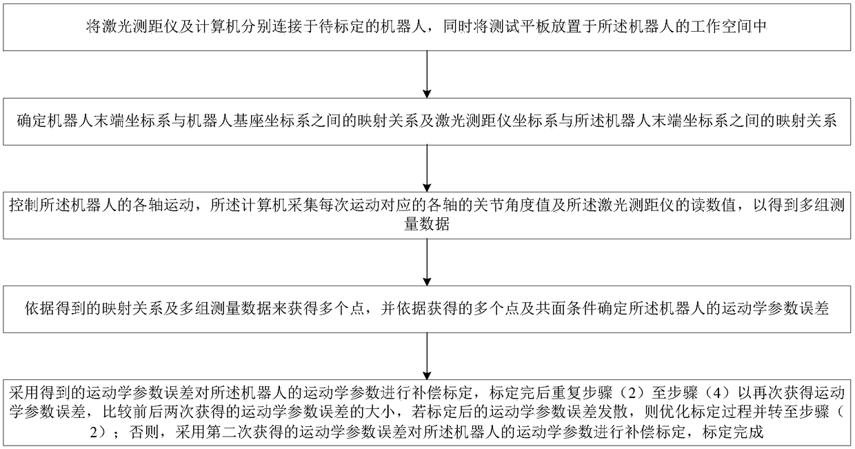
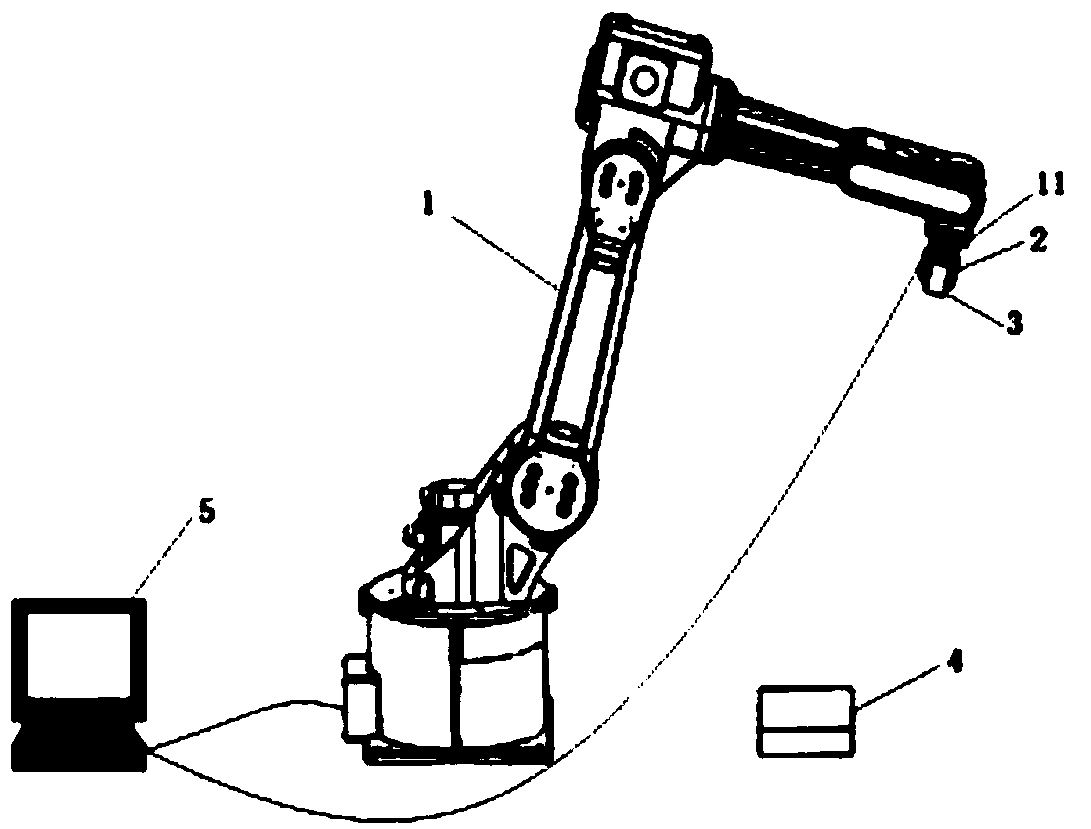
[0043] see figure 1 and figure 2 , the robot kinematics parameter calibration method based on the laser rangefinder provided by the preferred embodiment of the present invention, the operation of the robot kinematics parameter calibration method is simple, the calibration equipment used is relatively cheap, and also ensures the kinematics parameter calibration high precision.

[0044] The me...


PUM


Abstract

The invention belongs to the technical field of information measurement, and discloses a robot kinematics parameter calibration method based on a laser range finder. The method comprises the followingsteps that the laser range finder is connected to a to-be-calibrated robot, and a test flat plate is placed in the working space of the robot; (2) a mapping relation between a robot tail end coordinate system and a base coordinate system of the roboy and the mapping relation between a laser range finder coordinate system and the robot tail end coordinate system of the robot are determined; (3) ajoint angle value corresponding to each time of movement of the robot and a reading value of the laser range finder are gathered; (4) a plurality of points are obtained, and a kinematic parameter error is determined according to a coplane condition; and (5) compensation calibration is carried out on the kinematics parameters of the robot, the kinematics parameter error is acquired again after thecalibration is completed, the kinematics parameter error is compared with the value of the last time, and then calibration completion or re-calibration is determined. According to the method, the measuring efficiency is high, the operation is simple, the implementation is easy, and the accuracy is high.

Description

technical field [0001] The invention belongs to the technical field related to information measurement, in particular to a method for calibrating robot kinematics parameters based on a laser range finder. Background technique [0002] With the continuous expansion of the installed capacity and application range of industrial robots (hereinafter referred to as robots), the industry has put forward higher requirements for the performance of robots in all aspects, especially the pose accuracy of robots, such as absolute positioning accuracy and repeat positioning precision. At present, the repeated positioning accuracy of industrial robots is very high, which can reach 0.1 mm, but its absolute positioning accuracy is very poor, which can only reach the order of centimeters. This accuracy is far from meeting the control requirements of industrial sites, resulting in low robot positioning accuracy. The reason for the relatively large error is the geometric error of the robot in ...

Claims


Application Information

Patent Timeline
Patent Type & Authority Applications(China)
IPC IPC(8): B25J19/00G01B11/02
CPCB25J19/0095G01B11/02
Inventor 王坤朱志红周星罗健黄石峰高培阳
Owner HUAZHONG UNIV OF SCI & TECH
Why Eureka
Try Eureka