Hollow tire mold core, hollow tire based on mold core and tire manufacturing method

A manufacturing method and hollow technology are applied in the field of hollow tires and tire manufacturing, and hollow tire mold cores, which can solve the problems of poor wear resistance of non-pneumatic tires, not easy to clean, and high manufacturing costs, so as to reduce harmful gas emissions and avoid heat loss. and process flow costs, the effect of reducing scrap rate

Pending Publication Date: 2019-02-12
ANHUI GVG NEW MATERIAL CO LTD
View PDF6 Cites 2 Cited by
  • Summary
  • Abstract
  • Description
  • Claims
  • Application Information

AI Technical Summary

Problems solved by technology

[0010] Aiming at the above technical problems of non-pneumatic tires in the prior art, such as poor wear resistance, high secondary processing cost, poor comfort and difficult cleaning, the present invention provides a hollow tire mold core and a hollow tire based on the mold core. and tire manufacturing method

Method used


Image

  • Hollow tire mold core, hollow tire based on mold core and tire manufacturing method
  • Hollow tire mold core, hollow tire based on mold core and tire manufacturing method
  • Hollow tire mold core, hollow tire based on mold core and tire manufacturing method

Examples


Embodiment 1

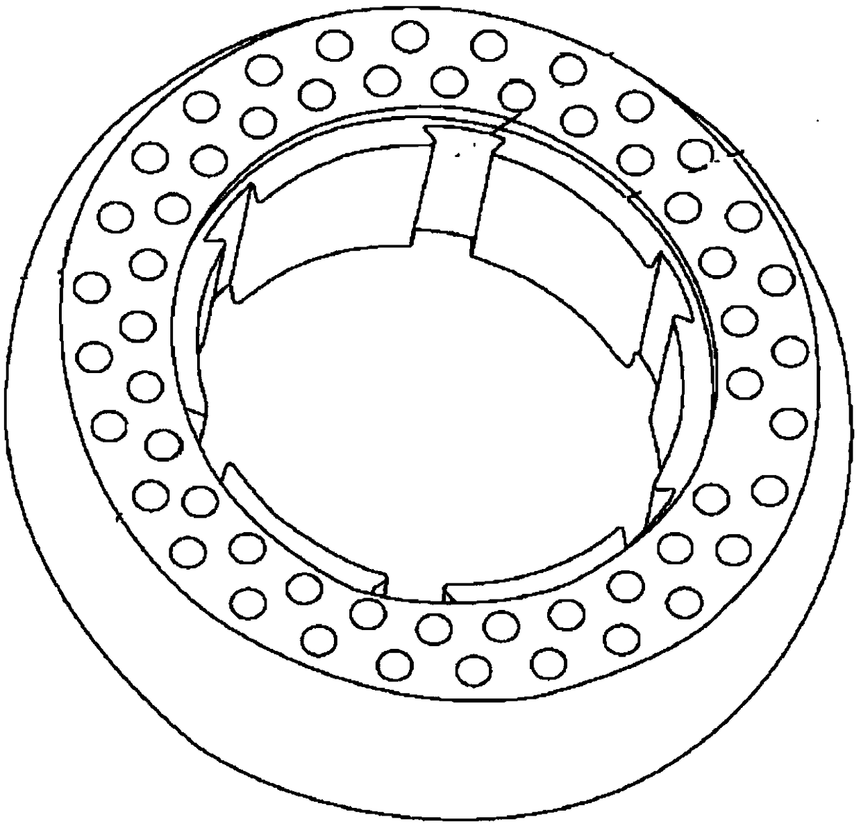
[0059] The hollow tire mold core 2 of this embodiment is applied to Figure 5 As shown in the cavity of the hollow and vulcanization molding device 1, such as Image 6 , 7 , 8, including a square core plate 21 and a circular upper core 22 and a lower core 23 arranged symmetrically on the upper and lower ends of the core plate 21; the upper core 22 and the lower core 23 The combined shape and size are as Picture 9 The cavity 33 of the hollow tire 3 shown is uniform.

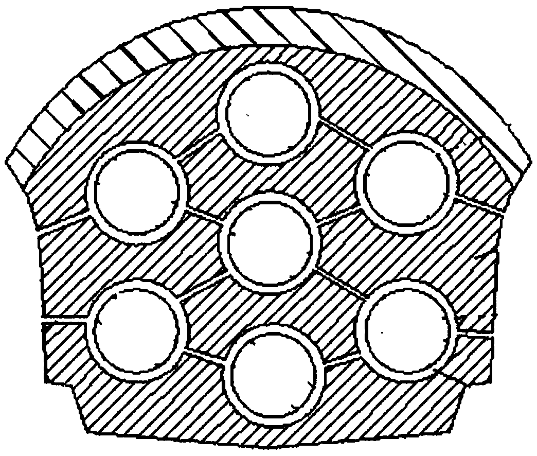
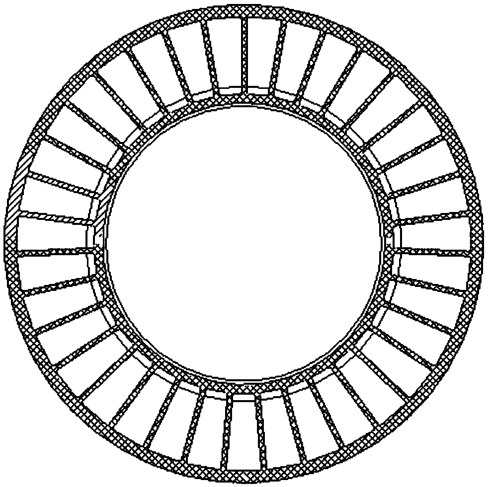
[0060] The hollow tire 3 of this embodiment based on the above hollow tire core 2 is such as Picture 9 , 10 The shown includes a circular carcass 31 and a hollow inner cavity 33; the inner cavity 33 is provided with a tire frame 32 along the circular direction; the tire frame 32 can be in the shape of a wine barrel, a wheat ear, a propeller or a cross The grid shape, etc., in this embodiment is a series-connected wine barrel arch shape, which is consistent with the series-connected wine barrel arch shape of the comb...

Embodiment 2

[0063] The basic structure of the hollow tire mold core 2 of this embodiment is the same as that of the embodiment 1. The difference and improvement are as follows: Figure 7 As shown, the mold core plate 21 in the upper mold core 22 and the lower mold core 23 protrudes outwardly to form a mold core ring protrusion 24 forming a gas channel 33 in the hollow tire 3;

[0064] The hollow tire 3 of the present embodiment based on the above hollow tire mold core 2 has an annular convex mold core 24. An annular gas channel 34 can be reserved at the annular center of the hollow tire 3. If the hollow tire 3 needs to be inflated, pass through the gas channel 34 communicates with the inner cavity 33 of the hollow tire 3.

[0065] The manufacturing method of the hollow tire 3 of this embodiment, the specific steps are:

[0066] Step 1. Rubber plasticization: The rubber particles are plasticized in the plasticizing injection screw, and the plasticized fluid rubber is temporarily stored in the pla...

Embodiment 3

[0076] The basic structure of the hollow tire core 2 and the core-based hollow tire 3 of this embodiment is the same as that of the second embodiment. The difference and improvement lies in that the upper end surface edge of the core plate 21 of the hollow tire core 2 is provided with positioning grooves. , It can facilitate the positioning of the upper mold half, the lower mold half and the hollow tire mold core 2 when they are closed.

[0077] The hollow tire 3 and tire manufacturing method of this embodiment, the basic steps are the same as that of embodiment 2, the production is as Picture 9 The inner cavity shown is a barrel-shaped tyre with a diameter of 200mm in series, and the specific steps are:

[0078] Step 1. Rubber plasticization: plasticize recycled rubber particles of crosslinkable waste rubber in a plasticizing injection screw. The plasticized fluid rubber is temporarily stored in the plasticizing cavity, and the plasticizing temperature is 60°C. , The purpose is t...


PUM

PropertyMeasurementUnit
diameteraaaaaaaaaa
diameteraaaaaaaaaa
diameteraaaaaaaaaa

Abstract

The invention discloses a hollow tire mold core, a hollow tire based on the mold core and a tire manufacturing method and belongs to the technical field of hollow tire technologies. The hollow tire mold core comprises a mold core plate, an upper mold core body and a lower mold core body, wherein the upper mold core body and the lower mold core body are symmetrically arranged on the upper end faceand the lower end face of the mold core plate. The shape and the size of the combination of the upper mold core body and the lower mold core body are consistent with those of an inner cavity of the hollow tire. The hollow tire comprises a round tire body and a hollow inner cavity. A tire skeleton is arranged in the ring direction of the inner cavity. The tire skeleton is in a barrel arch shape, ora wheat ear shape, or a propeller shape or an intersecting grid shape. The sealing manner is adopted in the periphery of the tire skeleton, on one hand, the situation that large air resistance is generated easily in the driving process of the tire can be avoided, and on the other hand, the situations that impurities such as various stones and sludge accumulate easily and cannot be washed easily,in the high-speed driving process, parts of the impurities are thrown out easily, and danger is caused can be effectively avoided. Injection forming, hollowing and vulcanizing devices of the hollow tire are integrated, and the cost expense of production of the hollow tire is reduced.

Description

Technical field [0001] The invention belongs to the technical field of rubber product technology, and specifically relates to a hollow tire mold core, a hollow tire based on the mold core, and a tire manufacturing method. Background technique [0002] In the prior art non-pneumatic tire products, the tire materials generally have at least two systems, one is SBS (styrene-based thermoplastic elastomer) and SEBS (polystyrene as the terminal segment, polybutadiene The ethylene-butene copolymer obtained by hydrogenation is a linear triblock copolymer with a mid-elastic block). The physical and chemical "crystallization" system (Mobike, such as figure 1 In the tire shown, the pores are longitudinal holes); a chemical reaction method "cross-linking" system based on PU (polyurethane), RB (rubber) and other polymer materials as raw materials (Harrow bicycles, such as figure 2 In the tire section shown, the pores are horizontal annular holes). Both systems can be injection molded by melt ...

Claims


Application Information

Patent Timeline
Patent Type & Authority Applications(China)
IPC IPC(8): B29C45/16B29C45/26B29C45/34B29C45/67B29C35/04B29C33/76B29D30/06B60C5/20
CPCB29D30/0606B29D30/0678B60C5/20B29D2030/0675B29D2030/0607
Inventor 叶孙勇葛九敢黎广赵正唐帆强金凤蒋水金何国柱王闯费大壮
Owner ANHUI GVG NEW MATERIAL CO LTD
Why Eureka
Try Eureka