Optical instantaneous frequency measurement device

A technology of instantaneous frequency and measurement devices, which is applied in the field of optical instantaneous frequency measurement devices, can solve the problems affecting system delay and the inability to measure multiple frequency signals at the same time, and achieve the effect of increasing bandwidth

Inactive Publication Date: 2019-02-12
SHANGHAI JIAO TONG UNIV
View PDF5 Cites 4 Cited by
  • Summary
  • Abstract
  • Description
  • Claims
  • Application Information

AI Technical Summary

Problems solved by technology

However, most frequency-energy mapping schemes cannot measure multiple frequency signals at the same time, and the measured results are related to the amplitude of the signal to be measured. It is necessary to control the amplitude of the signal to be measured to ensure the corresponding relationship between frequency and energy (see Zhou F ,Chen H,Wang X,et al.Photonic Multiple Microwave Frequency Measurement Based on Frequency-to-Time Mapping[J].IEEE Photonics Journal,2018,10(2):1-7.)
Most of the frequency-time mapping schemes adopt the method of optical carrier or optical filter time-domain sweep (see Ye C, Fu H, Zhu K, et al. All-Optical Approach to Microwave Frequency Measurement With Large Spectral Range and High Accuracy[J]. IEEE Photonics Technology Letters,2012,24(7):614-616.), but the frequency sweep rate will affect the system delay

Method used


Image

  • Optical instantaneous frequency measurement device
  • Optical instantaneous frequency measurement device
  • Optical instantaneous frequency measurement device

Examples


Embodiment 1

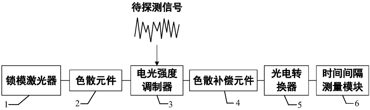
[0020] The system block diagram of this embodiment is as follows figure 1 As shown, it can be seen from the figure that the optical instantaneous frequency measurement device of the present invention includes: a mode-locked laser 1 , a dispersion element 2 , an electro-optic intensity modulator 3 , a dispersion compensation element 4 , a photoelectric converter 5 and a time interval measurement module 6 .

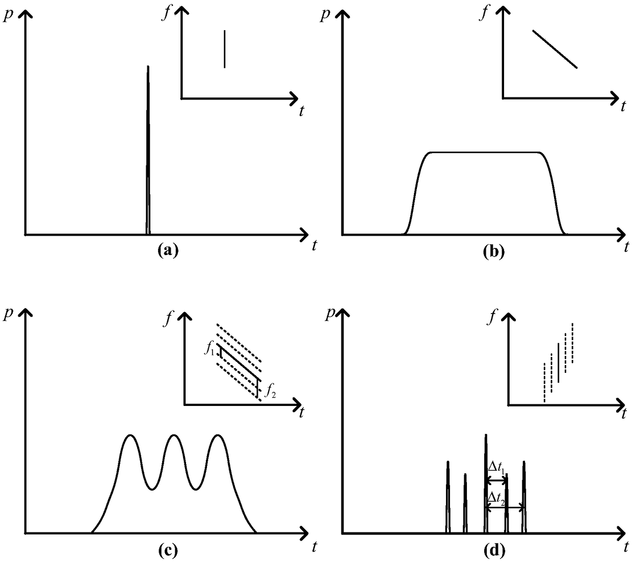
[0021] The central wavelength of the mode-locked laser 1 is λ, and the generation period is T s The optical pulse train, a single pulse contains the various components of the spectrum aligned in the time domain, such as figure 2 (a) shown.

[0022] The dispersion element 2 is an ordinary single-mode optical fiber with a certain length, and the amount of dispersion introduced is D 1 , the optical pulse will be stretched, and each spectral component of the optical signal after stretching will introduce different delays, and output a chirped optical signal, such as figure...

Embodiment 2

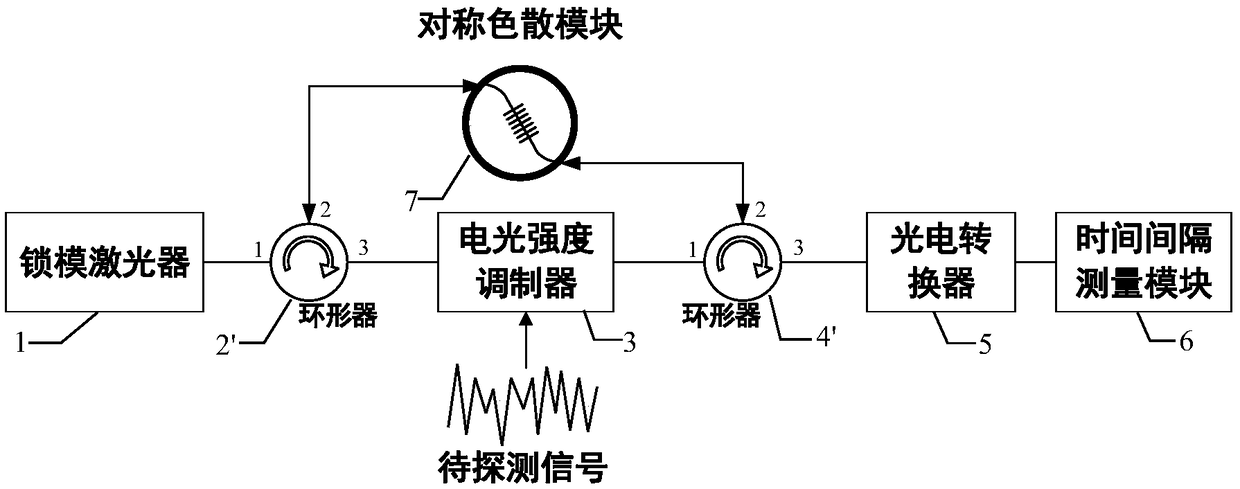
[0030] The system block diagram of this embodiment is as follows image 3 As shown, it can be seen from the figure that the optical instantaneous frequency measuring device of the present invention includes: a mode-locked laser 1, a first circulator 2', a symmetrical dispersion module 7, an electro-optical intensity modulator 3, a second circulator 4', and a photoelectric converter 5 and time interval measurement module6.

[0031] The central wavelength of the mode-locked laser 1 is λ, and the generation period is T s The optical pulse sequence is sent to the symmetrical dispersion module 7 by the first circulator 2', and the symmetrical dispersion module 7 is a linearly chirped fiber Bragg grating.

[0032] The symmetrical dispersion module 7 introduces a dispersion amount D to the left input light 1 , stretch the optical pulse, and reflect the stretched optical signal back to the first circulator 2'.

[0033] The electro-optical intensity modulator 3 adopts a microring modu...


PUM


Abstract

The invention relates to an optical instantaneous frequency measurement device. The optical instantaneous frequency measurement device sequentially comprises a mode-locked laser, a dispersion component, an electro-optical intensity modulator, a dispersion compensation component, a photoelectric converter and a time interval measurement module. According to the optical instantaneous frequency measurement device in the invention, the limitation of an electronic device is broken through; the instantaneous frequency measurement bandwidth is greatly increased; simultaneously, compared with other optical instantaneous frequency measurement systems, the optical instantaneous frequency measurement device in the invention has the advantages that: multiple frequency signals can be measured at the same time; the measurement result has nothing to do with the input signal amplitude; and furthermore, the frequency sweeping process is unnecessary.

Description

technical field [0001] The invention relates to microwave signal frequency measurement, in particular to an optical instantaneous frequency measurement device. Background technique [0002] The frequency measurement of microwave signals plays an important role in the fields of electronic warfare, radar early warning, and electronic intelligence systems. However, with the development of communication technology and the explosive growth of data transmission capabilities, traditional electronic frequency measurement systems are difficult to meet the requirements of ultra-large instantaneous measurement. The urgent need for bandwidth (above 10GHz). The optical frequency measurement system has the advantages of large instantaneous bandwidth, anti-electromagnetic interference, light weight, etc., and can break through the limitations of the traditional electronic frequency measurement system. [0003] The existing optical frequency measurement techniques are mainly divided into t...

Claims


Application Information

Patent Timeline
Patent Type & Authority Applications(China)
IPC IPC(8): H04B10/079
CPCH04B10/0795
Inventor 吴龟灵王思同陈建平
Owner SHANGHAI JIAO TONG UNIV
Why Eureka
Try Eureka