
Gas pipe fitting automatic welding device

A technology for automatic welding and gas pipes, applied in auxiliary devices, welding accessories, welding equipment, etc., can solve problems such as narrow welding positions, failure to meet product quality, unstable quality, etc., to ensure welding quality, save labor costs, The effect of high transmission precision

Pending Publication Date: 2019-02-15
浙江金隆铜业股份有限公司
View PDF0 Cites 5 Cited by
  • Summary
  • Abstract
  • Description
  • Claims
  • Application Information

AI Technical Summary

Problems solved by technology

[0002] At present, the welding pipe fittings used in the market are mainly manual welding, the actual production process is inefficient, and manual welding may cause unstable quality due to personal skills and other factors
In addition, when welding gas pipe fittings, due to the difference of 3mm between the outer diameter of the steel ring and the outer diameter of the pipe, the welding position is very narrow, and it is not easy to weld manually.
During the welding process of the steel ring, the pipe fittings need to be rotated to achieve welding at different positions. With the current technology, the pipe fittings need to be rotated manually, which is time-consuming and labor-intensive, or the rotation cannot accurately start and fall on the pipe fittings, and accurate welding cannot be achieved. Product quality requirements, resulting in waste

Method used


Image

  • Gas pipe fitting automatic welding device
  • Gas pipe fitting automatic welding device
  • Gas pipe fitting automatic welding device

Examples


Embodiment Construction

[0020] The present invention will be further described in detail below in conjunction with the accompanying drawings, and specific implementation methods will be given.

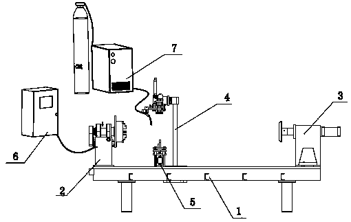
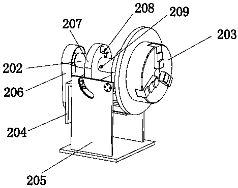
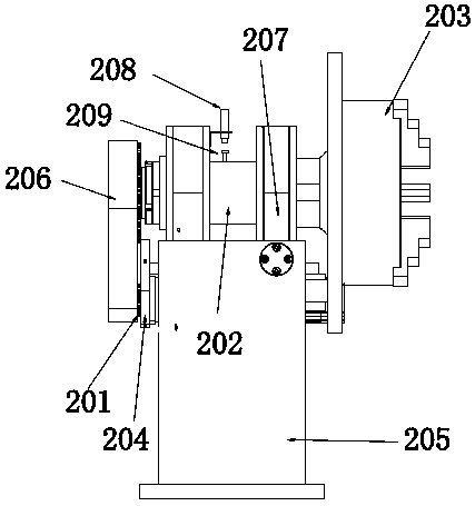
[0021] Such as figure 1 As shown, an automatic welding device for gas pipe fittings of the present invention includes a base 1, one end of the base 1 is the power end, the other end of the base 1 is the tail end, and the power end is equipped with a power head assembly 2 for fixing the welding end of the gas pipe fittings 1. The upper surface of the base 1 is provided with a slide rail, and the tail end is installed with a tailstock assembly 3 for tightening the other end of the gas pipe. The bottom of the tailstock assembly 3 is controlled by the tailstock cylinder to slide on the slide rail, and the air pressure As power, it is used to feed forward and press the steel ring to the metal pipe. The control switch of the tailstock cylinder is set on the ground for easy operation by stepping on it; There is als...


PUM


Abstract

The invention discloses a gas pipe fitting automatic welding device, which comprises a base. One end of the base is the power end, and the other end of the base is the tail end; a power machine head assembly body is installed at the power end, a sliding rail is formed in the upper surface of the base, a tailstock assembly body is installed at the tail end, the bottom of the tailstock assembly bodyis controlled by a tailstock air cylinder to slide on the sliding rail, a welding gun mechanism assembly body and an upper holding mechanismassembly body are further arranged between the power machine head assembly body and the tailstock assembly body on the base, the power machine head assembly body is connected with a PLC control box through wires, and the welding gun mechanism assembly body isconnected with a carbon dioxide protective welding machine. According to the gas pipe fitting automatic welding device, a rotating power machine head is adopted as a rotating power device of pipe fittings, and thus precise control of the required rotating angle can be realized; the tailstock assembly body is arranged, suitable adjustment can be carried out according to the specifications of the pipe fittings, manual movement is not required, and thus the labor cost is saved; and the welding gun mechanism assembly body is arranged, precision welding can be achieved, and the quality of weldingis ensured.

Description

technical field [0001] The invention belongs to the technical field of mechanical equipment, and in particular relates to an automatic welding device for gas pipe fittings. Background technique [0002] At present, the welding pipe fittings used in the market are mainly manual welding, the actual production process is inefficient, and manual welding may cause unstable quality due to personal skills and other factors. In addition, when welding gas pipe fittings, due to the difference of 3mm between the outer diameter of the steel ring and the outer diameter of the pipe, the welding position is very narrow, and it is not easy to weld manually. During the welding process of the steel ring, the pipe fittings need to be rotated to achieve welding at different positions. With the current technology, the pipe fittings need to be rotated manually, which is time-consuming and labor-intensive, or the rotation cannot accurately start and fall on the pipe fittings, and accurate welding ...

Claims


Application Information

Patent Timeline
Patent Type & Authority Applications(China)
IPC IPC(8): B23K37/047B23K37/02B23K37/053B23K9/16B23K9/32
CPCB23K9/16B23K9/32B23K37/02B23K37/047B23K37/053B23K37/0533
Inventor 金望政张杨林
Owner 浙江金隆铜业股份有限公司
Learn More