
Panel film laminating machine

A laminating machine and laminating technology, which is applied in wood processing appliances, joining of wooden veneers, wood layered products, etc., can solve the problems of easy disengagement, no plate splicing and clamping, and difficult lamination. , to achieve the effect of accurate rotation angle

Pending Publication Date: 2019-02-15
奥凯家居(浙江)有限公司
View PDF0 Cites 7 Cited by
  • Summary
  • Abstract
  • Description
  • Claims
  • Application Information

AI Technical Summary

Problems solved by technology

At present, in household production, the boards are often cut into various required shapes before lamination, and then laminated individually after preliminary processing. Because the shapes of the cut boards are different, it is difficult to carry out lamination.
For example, when covering the sharp corners, the film is difficult to compound on the sharp corners, and it is easy to come off
In the market, the most advanced lamination method is to combine the cut boards and then carry out lamination processing, and then cut them. This kind of lamination effect is the most ideal, but many laminating machines do not have the ability to cut The function of splicing and clamping the final plates

Method used


Image

  • Panel film laminating machine
  • Panel film laminating machine

Examples


Embodiment Construction

[0014] The present invention will be further described in detail below in conjunction with the accompanying drawings and examples. The following examples are explanations of the present invention and the present invention is not limited to the following examples.

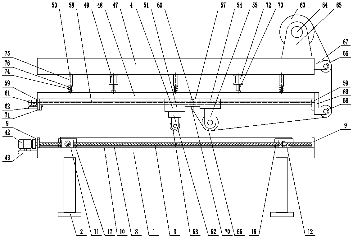
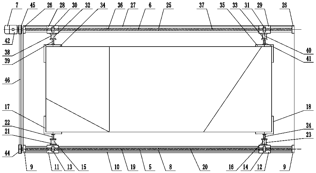
[0015] Such as figure 1 and figure 2 As shown, a sheet laminating machine includes a laminating platform 1, a laminating leg 2, an assembly clamping device 3, and a glue coating device 4, and the laminating leg 2 is arranged on the laminating platform 1 Below, the assembling and clamping device 3 includes a front assembling mechanism 5, a rear assembling mechanism 6, and an assembling driving mechanism 7. Mechanism 5 comprises front assembling screw mandrel 8, front assembling screw mandrel bearing 9, front assembling guide rail 10, first front assembling slider 11, second front assembling slider 12, first front assembling screw nut 13, second front assembling Assembling the screw nut 14, the first front assembli...


PUM


Abstract

The invention provides a panel film laminating machine, and belongs to the technical field of house and home production. The panel film laminating machine comprises a splicing clamping device and a gluing film laminating device. The splicing clamping device comprises a front splicing mechanism, a rear splicing mechanism and a splicing drive mechanism. The gluing film laminating device is arrangedon the upper side of a film laminating platform. A gluing sliding block and a film laminating sliding block of the gluing film laminating device are connected through a synchronous sliding block. A gluing film laminating lead screw and a gluing film laminating lead screw nut are in threaded connection. A gluing lifting support is arranged at the lower end of the gluing sliding block. A gluing roller is rotationally arranged on the gluing lifting support. The film laminating support is arranged at the lower end of the film laminating sliding block. A film laminating roller is rotationally arranged on the film laminating support. A film clamping device is arranged below the synchronous sliding block, and a clamping device travel switch is arranged on a left gluing film laminating lead screwsupport. By means of the panel film laminating machine, cut panels can be subjected to film laminating processing after being spliced and clamped again, the structure is reasonable, the film laminating effect is good, the panel film laminating machine can be applicable to different sizes of panels, applicability is high, and reliability is good.

Description

technical field [0001] The invention relates to the technical field of household production, in particular to a plate laminating machine. Background technique [0002] Board is a very important base material in home production. Panels are flat, rectangular panels of building material made into standard sizes and used in the construction industry as elements for walls, ceilings or floors. The board can be divided into: solid wood board, large core board, bamboo jigsaw board, density board, veneer, thin core board, finger joint board, melamine board, waterproof board, gypsum board, cement board, baking varnish board, particle board, etc. Board processing technology includes basic processing technologies such as wood cutting, wood drying, wood gluing, and wood surface decoration, as well as functional treatment technologies such as wood protection and wood modification. There are sawing, planing, milling, drilling, sanding and other methods for plate cutting. Due to the influ...

Claims


Application Information

Patent Timeline
IPC IPC(8): B27D1/04B32B21/00
CPCB27D1/04B32B21/00
Inventor 沈军朱洪强
Owner 奥凯家居(浙江)有限公司
Learn More