
Biomass gasification power generation system and method

A power generation system, biomass technology, applied in gasification process, granular/powdered fuel gasification, production of combustible gas, etc., to achieve the effect of flexible operation, high system efficiency and compact structure

Pending Publication Date: 2019-02-15
SHANGHAI POWER EQUIP RES INST
View PDF0 Cites 2 Cited by
  • Summary
  • Abstract
  • Description
  • Claims
  • Application Information

AI Technical Summary

Problems solved by technology

This type of power generation system has not been reported in the industry

Method used


Image

  • Biomass gasification power generation system and method

Examples


Embodiment Construction

[0035] Below in conjunction with specific embodiment, further illustrate the present invention.

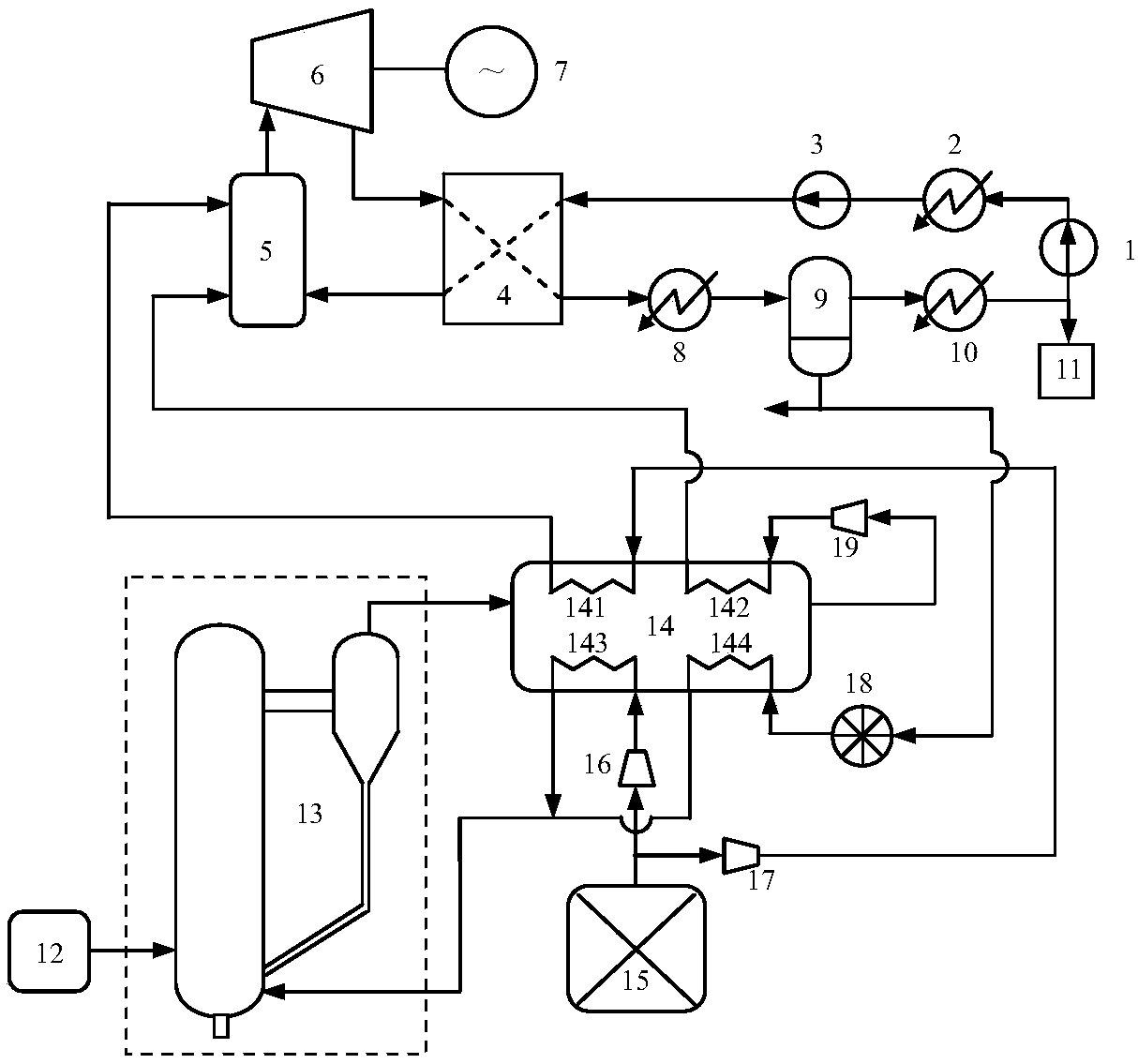
[0036] figure 1 The schematic diagram of the biomass gasification power generation system provided in this embodiment includes a biomass gasification subsystem and a semi-closed supercritical carbon dioxide circulation subsystem.

[0037] The biomass gasification subsystem includes a feeding device 12, the outlet of the feeding device 12 is connected to the feed port of the biomass gasification furnace 13, and the gas outlet of the biomass gasification furnace 13 is connected to the gas inlet of the gas purification and cooling device 14. The outlet of the oxygen source 15 is divided into two paths, one path is connected to the inlet of the oxygen compressor 16 of the biomass gasifier, and the other path is connected to the inlet of the oxygen compressor 17 of the combustion chamber.

[0038] The gas purification and cooling device 14 is provided with a gas inlet and a gas outlet...


PUM


Abstract

The invention provides a biomass gasification power generation system. The biomass gasification power generation system comprises a biomass gasification subsystem and a semi-closed supercritical carbon dioxide circulation subsystem, wherein the biomass gasification subsystem comprises a feeding device, a biomass gasifier, a fuel gas purification and cooling device, an oxygen source, a gasifier oxygen feeding compressor, a combustion chamber oxygen feeding compressor, a hydraulic turbine, a fuel gas compressor and the like; and the supercritical carbon dioxide circulation subsystem comprises afirst carbon dioxide pump, a middle cooler, a second carbon dioxide pump, a heat regenerator, a combustion chamber, a turbine, a power generator, a cooler, a water separator, a condenser, a carbon dioxide collection device and the like. The invention further provides a biomass gasification power generation method. The biomass gasification power generation system is high in efficiency, semi-closedsupercritical carbon dioxide is circulated under high-temperature and high-pressure parameters, so that the power generation efficiency is high; negative carbon dioxide emissions are achieved, so thatan additional carbon capturing device is avoided; and the system is simple, compact in structure and flexible to operate, so that a small or large chimney-free biomass gasification power plant can beestablished.

Description

technical field [0001] The invention relates to a biomass gasification power generation system and method, and belongs to the technical field of new energy power generation. Background technique [0002] According to a report issued by the United Nations Intergovernmental Panel on Climate Change (IPCC), if the global greenhouse effect develops at the current rate, the world's average temperature will be 1.5 degrees higher than before the industrial revolution between 2030 and 2052. Therefore, the rapid development of zero-carbon emission power generation technology will become an urgent social demand. [0003] Biomass is one of the important renewable energy sources. It has the advantages of rich resources, renewable, wide distribution, and less air pollutant emissions. Both at home and abroad are vigorously developing biomass energy power generation technology. Biomass power generation technologies mainly include direct combustion power generation, mixed combustion power g...

Claims


Application Information

Patent Timeline
IPC IPC(8): C10J3/00C10J3/20C10J3/56C10J3/50C10J3/48C10J3/72
CPCC10J3/00C10J3/20C10J3/48C10J3/50C10J3/56C10J3/72C10J2300/0959C10J2300/0953Y02P20/54
Inventor 郑开云黄志强
Owner SHANGHAI POWER EQUIP RES INST
Learn More