
Biogas slurry waste heat recycling and utilization system and working method

A technology of waste heat recovery and biogas slurry, which is applied in the field of biogas slurry waste heat recovery and utilization system, can solve the problems of low heat energy recovery rate of biogas slurry, achieve the effect of improving heat exchange response speed, increasing heat exchange contact area, and improving heat exchange efficiency

Pending Publication Date: 2019-02-15
ENERGY & ENVIRONMENT RES INST OF HEILONGJIANG PROVINCE
View PDF0 Cites 1 Cited by
  • Summary
  • Abstract
  • Description
  • Claims
  • Application Information

AI Technical Summary

Problems solved by technology

[0004] In order to solve the problem of low heat energy recovery rate of the existing biogas slurry, the present invention provides a biogas slurry waste heat recovery and utilization system and working method

Method used


Image

  • Biogas slurry waste heat recycling and utilization system and working method

Examples


Embodiment 1

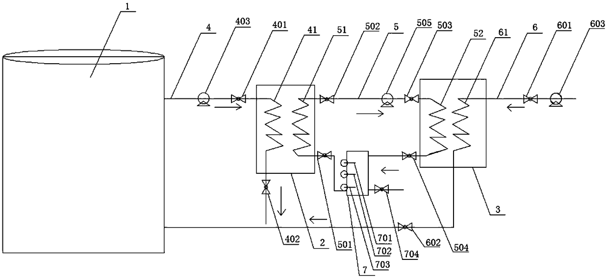
[0035] Biogas slurry waste heat recovery and utilization system, including fermenter reactor 1, evaporator 2, condenser 3, biogas slurry discharge pipeline 4, heat medium circulation pipeline 5 and raw material feed pipeline 6;

[0036] The biogas slurry discharge pipeline 4 communicates with the interior of the fermenter reactor 1, and is provided with a first valve 401, a second valve 402 and a discharge pump 403;

[0037] The raw material feed pipeline 6 communicates with the interior of the fermenter reactor 1, on which a third valve 601, a fourth valve 602 and a feed pump 603 are arranged;

[0038] The heat supply section 41 of the biogas slurry discharge pipeline 4 and the heat absorption section 51 of the heat medium circulation pipeline 5 are fixedly arranged in the evaporator 2 together;

[0039] The heat release section 52 of the heat medium circulation pipeline 5 and the heat exchange section 61 of the raw material feed pipeline 6 are fixedly arranged in the condens...

Embodiment 2

[0045] In this embodiment, on the basis of Embodiment 1, an upper liquid level sensor 701 and a lower liquid level sensor 702 are provided in the heat medium buffer tank 7, and the upper liquid level sensor 701 communicates with the controller to control the heat-absorbing water outlet valve 502. Opening of the heat release water inlet valve 503 and the fan 505; the lower liquid level sensor 702 is connected with the controller to control the closing of the heat absorption water inlet valve 501 and the heat release water outlet valve 504.

[0046] The liquid level sensors used in this embodiment are all float type liquid level sensors, and the controller model is Siemens S7-200SMART controller.

[0047]The biogas slurry waste heat recovery and utilization system provided in this embodiment is connected to the controller through the upper liquid level sensor and the lower liquid level sensor set in the heat medium buffer tank, and controls the automatic operation of the correspo...

Embodiment 3

[0049] In this embodiment, on the basis of Embodiment 2, a fluid replenishment sensor 703 and a fluid injection valve 704 are further provided on the heat medium buffer tank 7 . The liquid replenishment sensor used in this embodiment is a float type liquid level sensor.

[0050] The biogas slurry waste heat recovery and utilization system provided in this embodiment monitors the liquid heat medium storage in the heat medium buffer tank through the liquid replenishment sensor installed in the heat medium buffer tank, and maintains continuous recovery and utilization of biogas slurry waste heat.


PUM


Abstract

The invention relates to a biogas slurry waste heat recycling and utilization system and a working method, and belongs to the technical field of biogas engineering. To solve the problem that conventional biogas slurry is low in heat energy recycling rate, the invention provides the biogas slurry waste heat recycling and utilization system which comprises a fermentation tank reactor, an evaporator,a condenser, a biogas slurry discharge pipeline, a heating medium circulation pipeline and a raw material feeding pipeline; a liquid heating medium is fed into a heat suction section of the heating medium circulation pipeline, and is used for absorbing heat of biogas slurry in the biogas slurry discharge pipeline under the action of negative pressure, and the heat is evaporated into a gas; a gasheating medium is fed into a heat discharge section of the heating medium circulation pipeline and is liquidized under the action of positive pressure; and raw materials in the raw material feeding pipeline absorb heat released when the gas heating medium is liquidized to complete heating. By adopting the system, the heat exchange contact area is increased through the heating medium circulation pipeline, the heat exchange response speed of biogas slurry and the raw materials is increased, the heat exchange efficiency of biogas slurry waste heat recycling and utilization is improved, and meanwhile, fermented raw materials are heated by virtue of biogas slurry waste heat, and the energy consumption for preheating the raw materials in common biogas fermentation can be reduced.

Description

technical field [0001] The invention belongs to the technical field of biogas engineering, and in particular relates to a system and a working method for recovering and utilizing waste heat from biogas liquid. Background technique [0002] As a clean biomass energy, biogas integrates environmental benefits and economic benefits. Its development and utilization is an effective measure to solve the problem of energy supply under the situation of energy shortage. Biogas is produced by the fermentation of organic matter by anaerobic microorganisms at a suitable temperature, and temperature is a key factor in biogas fermentation. If the fermentation temperature is low, the activity of anaerobic microorganisms will be low, resulting in low project operation efficiency and low energy efficiency. [0003] In large-scale biogas projects, in order to ensure the normal fermentation and production of biogas, the fermentation temperature must be stable within a certain range. Therefore...

Claims


Application Information

Patent Timeline
IPC IPC(8): C12M1/02C12M1/107F28D15/02
CPCF28D15/0266C12M21/04C12M41/18Y02E50/30
Inventor 周闯刘伟王欣秦国辉王玉鹏徐晓秋罗向东李福裿
Owner ENERGY & ENVIRONMENT RES INST OF HEILONGJIANG PROVINCE
Learn More