A high power density flow battery

A high power density, flow battery technology, used in fuel cells, regenerative fuel cells, circuits, etc., can solve problems such as insufficient use of electrolyte, difficulty in improving power density, and easy occurrence of dead zone distribution, and improve battery operation. Efficiency, reducing ohmic internal resistance, and the effect of large internal and external hydraulic pressure differences

Active Publication Date: 2022-02-15
NARI TECH CO LTD +2
View PDF6 Cites 0 Cited by
  • Summary
  • Abstract
  • Description
  • Claims
  • Application Information

AI Technical Summary

Problems solved by technology

During operation, due to the flow of electrolyte between the flat electrodes, dead zones are prone to occur, and dead zones or uneven distribution are prone to occur, so that the electrolyte cannot be fully utilized.
In addition, this kind of battery is limited by factors such as the filling density of the separation membrane and the electrode, the contact between the electrolyte and the electrode, and the charge exchange between the positive and negative electrolytes. It is difficult to increase the power density and there is a bottleneck.

Method used


Image

  • A high power density flow battery
  • A high power density flow battery
  • A high power density flow battery

Examples


Embodiment Construction

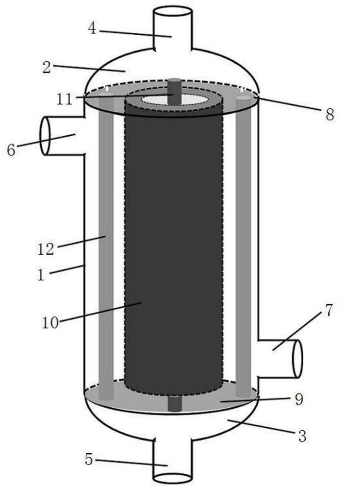
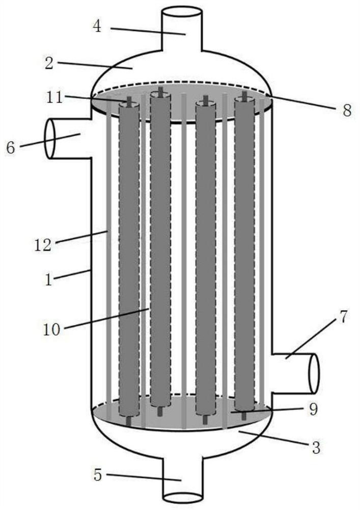
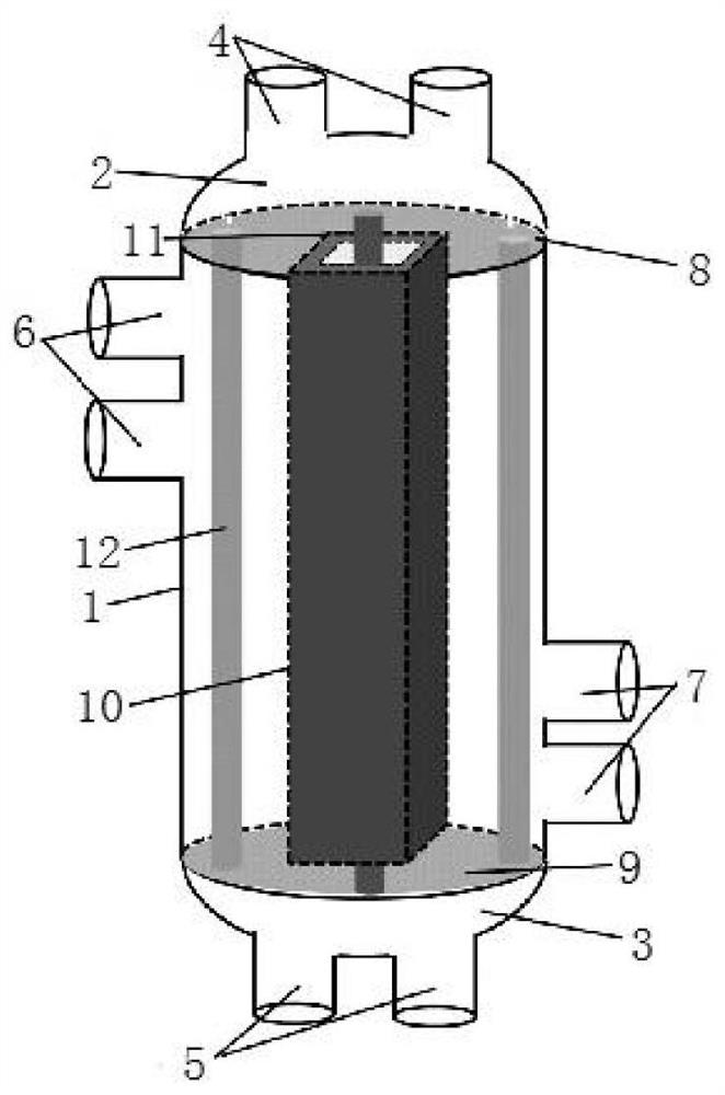
[0018] Such as figure 1 , for a single-tube membrane zinc-bromine flow battery, a hollow separation membrane 10 is placed inside the cylinder body 1, and the two ends of the hollow separation membrane 10 are respectively connected to the upper end seal 8 and the lower end seal 9, wherein the upper end seal 8 and the lower end seal 9 Connect the inside of the cylinder 1 with the outside of the hollow separation membrane 10, the two ends of the cylinder 1 are respectively connected with the upper head 2 and the lower head 3, wherein the upper head 2 has a first electrolyte inlet 4, and the lower head 3 has a There is a first electrolyte outlet 5, a positive or negative first electrode 11 is located inside the hollow separation membrane 10, and two corresponding positive or negative second electrodes 12 are located outside the hollow separation membrane 10 and inside the cylinder 1, and the hollow separation The membrane 10 is a tubular separation membrane. There is a second ele...


PUM

PropertyMeasurementUnit
pore size distributionaaaaaaaaaa
lengthaaaaaaaaaa
thicknessaaaaaaaaaa

Abstract

The invention discloses a liquid flow battery with high power density, which comprises a cylinder body and an upper seal head and a lower seal head respectively connected to the cylinder body. The upper seal head is provided with a first electrolyte inlet, and the lower seal head is provided with a first electrolyte inlet. The electrolyte outlet, the second electrolyte inlet and the second electrolyte outlet are set on the cylinder body, the upper end seal and the lower end seal are respectively installed at the end of the cylinder body, the upper end seal and the lower end seal are respectively connected with the hollow separation membrane, and the inside of the hollow separation membrane is set The first electrode, the second electrode is arranged on the outer side of the hollow separation membrane and the inner side of the cylindrical body. The electrode filling density of the liquid flow battery of the present invention is larger, and the contact area between the electrolyte and the electrode is larger, so that the electrochemical reaction can be performed more rapidly on the electrode surface, and the electrochemical polarization of the battery is reduced. The tubular separation membrane of the flow battery can be filled with a large density by using a hollow fiber membrane with a small diameter, which increases the membrane area per unit volume inside the battery and increases the power density of the battery per unit volume.

Description

technical field [0001] The invention relates to a flow battery, in particular to a flow battery with high power density. Background technique [0002] Zinc-bromine flow battery is a new type of large-scale electrochemical energy storage technology, which realizes the mutual conversion between electrical energy and chemical energy through the change of valence state of reactive substances. In a flow battery, the active material is stored in the electrolyte and has mobility. Flow batteries are generally composed of stacks, electrolytes and their storage tanks, pumps and other piping systems. The stacks are mainly composed of separation membranes (including ion-conducting membranes, microporous nanofiltration membranes, etc.), positive or negative electrodes, and current collectors. board etc. During the working process of the battery, the separation membrane plays the role of separating the positive and negative electrodes of the battery to prevent internal short circuit or ...

Claims


Application Information

Patent Timeline
Patent Type & Authority Patents(China)
IPC IPC(8): H01M8/18
CPCH01M8/184Y02E60/50
Inventor 何振宇李欣杨冬梅曾雨竹陈永华吕宏水杨志宏朱金大
Owner NARI TECH CO LTD
Why Eureka
Try Eureka