A USB data real-time monitoring system and method based on FPGA
A monitoring system and data technology, applied in the direction of electrical digital data processing, multiple digital computer combinations, digital computer components, etc., can solve the problem of not allowing real-time monitoring of data
- Summary
- Abstract
- Description
- Claims
- Application Information
AI Technical Summary
Problems solved by technology
Method used
Image
Examples
Embodiment 1
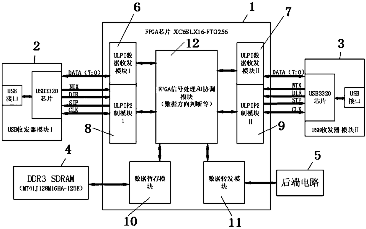
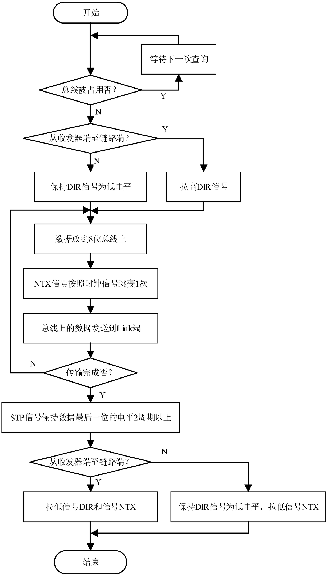
[0053] Embodiment 1: as Figure 1-2 As shown, an FPGA-based USB data real-time monitoring system includes an FPGA chip 1, a USB transceiver module Ⅰ 2, a USB transceiver module Ⅱ 3, and a DDR3 SDRAM memory 4;
[0054] The FPGA chip 1 includes: ULPI data transceiver module I6, ULPI data transceiver module II7, ULPI control module I8, ULPI control module II9, data temporary storage module 10 and FPGA signal processing and coordination module 12;
[0055] The FPGA chip 1 is connected to the USB transceiver module I2, the USB transceiver module II3, and the DDR3 SDRAM memory 4; the USB transceiver module I2 and the USB transceiver module II3 are connected to the FPGA chip 1 and the USB transceiver module through different I / O ports Ⅰ2 through ULPI data transceiver module Ⅰ6, ULPI control module Ⅰ8 and FPGA signal processing and coordination module 12; FPGA signal processing and coordination module 12 is connected with DDR3 SDRAM memory 4 through data temporary storage module 10, F...
Embodiment 2
[0073] Embodiment 2: as Figure 1-2 Shown, a kind of FPGA-based USB data real-time monitoring system and method, including this embodiment is the same as embodiment 1, wherein, further:
[0074] In this example, the back-end circuit 5 is an FPGA-based astronomical real-time imaging system, and the USB transceiver module I2 is connected to a CCD camera. The realized function is that the PC connected to the USB transceiver module Ⅱ3 can receive the astronomical images taken by the CCD camera, and at the same time, the back-end real-time processing circuit can process the transmitted images in real time with the lucky imaging algorithm, and finally got the answer.
[0075] The USB transceiver module Ⅱ3 connects the slave device to the PC, and works in the slave device mode, that is, the USB transceiver module Ⅱ3 connects to the PC using the A-type interface; the USB transceiver module Ⅰ2 connects to the CCD camera, works in the host mode, and uses USB transceiver Connect to the...
PUM
 Abstract
Description
Claims
Application Information
 - R&D
- Intellectual Property
- Life Sciences
- Materials
- Tech Scout
- Unparalleled Data Quality
- Higher Quality Content
- 60% Fewer Hallucinations
Browse by: Latest US Patents, China's latest patents, Technical Efficacy Thesaurus, Application Domain, Technology Topic, Popular Technical Reports.
© 2025 PatSnap. All rights reserved.Legal|Privacy policy|Modern Slavery Act Transparency Statement|Sitemap|About US| Contact US: help@patsnap.com


