Novel lamination module

A laminated component and a new type of technology, applied in electrical components, semiconductor devices, capacitor parts, etc., can solve the problems of the stability of welding equipment and the immaturity of the matching degree of conductive materials, the limited power improvement of MBB technology, and the thin grid of cells. The problem of high line resistance can meet the requirements of high-efficiency components, improve market competitiveness, and expand the research and development route.

Pending Publication Date: 2019-02-19
LIANYUNGANG SHENZHOU NEW ENERGY
View PDF0 Cites 7 Cited by
  • Summary
  • Abstract
  • Description
  • Claims
  • Application Information

AI Technical Summary

Problems solved by technology

[0004] (1) The multi-busbar technology reduces the equivalent series resistance of the cells by increasing the busbars, and improves the photoelectric conversion efficiency of the cells. Module power, but the pure MBB technology has limited power improvement, and the packaging cost remains high;
[0005] (2) Lamination technology uses laser scribing technology to divide the battery into 1 / 5 or 1 / 6 pieces, and then use conductive glue and other conductive linking media to overlap the front and back of the battery according to the shingling method to form a The battery string without inter-sheet spacing can accommodate more battery sheets by saving the inter-sheet spacing, thereby increasing the effective power generation area of ​​the components and increasing the power of the assembly. Conductive material matching is still immature
[0006] Conventional modules are compatible with half-cut technology, but not with conventional lamination technology

Method used


Image

  • Novel lamination module
  • Novel lamination module
  • Novel lamination module

Examples


Embodiment Construction

[0018] The present invention will be further explained below in conjunction with the accompanying drawings and specific embodiments. It should be understood that the following specific embodiments are only used to illustrate the present invention and are not intended to limit the scope of the present invention. It should be noted that the words "front", "rear", "left", "right", "upper" and "lower" used in the following description refer to the directions in the drawings, and the words "inner" and "outer ” refer to directions towards or away from the geometric center of a particular part, respectively.

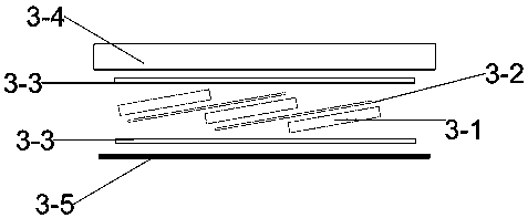
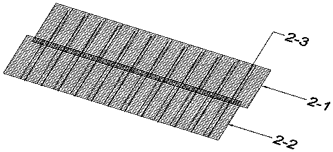
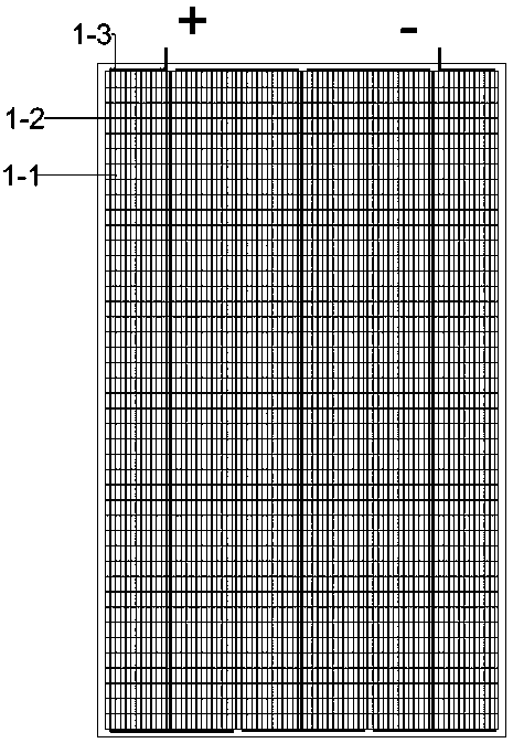
[0019] On the basis of traditional photovoltaic modules, the present invention introduces the design concept of laminated modules, and divides photovoltaic cells into 1 / 2, 1 / 3, 1 / 4, 1 / 5 or even smaller cells by using laser scribing means Slices, through ultra-thin ribbons, the diced battery slices are connected in series in a shingled manner to form a stacked battery string wit...


PUM


Abstract

The invention discloses a novel lamination module. The novel lamination module has the advantages that lamination module design ideas are introduced on the basis of the traditional photovoltaic modules, scribing technologies and ultrathin welding strips are applied, scribed small photovoltaic cell pieces are linked with one another by the ultrathin welding strips in the front-rear directions, front and rear cell pieces are arranged in an overlapped tile manner, and the overlap widths range from 2 mm to 4 mm; the novel lamination module is applicable to solar cells such as crystalline silicon cells, thin film cells, dye-sensitized cells and perovskite solar cells; currents of the cell pieces further can be reduced by the aid of laser scribing technologies, the scribed cell pieces are arranged in the overlapped tile manner, accordingly, the piece distances of the novel lamination module can be eliminated, the effective power generation area of the novel lamination module can be enlarged,and power of the novel lamination module can be increased; the thicknesses of overlapped regions of the cell pieces can be reduced by the aid of the ultrathin welding strips, the fragment rates of overlapped tile cell strings can be reduced, and the reliability of the novel lamination module can be improved; the novel lamination module is compatible with merits of lamination technologies, research and development thoughts can be expanded, research spaces can be enhanced, and the development potential of the novel lamination module can be exploited.

Description

technical field [0001] The invention belongs to the field of solar photovoltaic cells, and in particular relates to a novel stacked sheet assembly. Background technique [0002] As the cost of silicon materials and cells continues to decrease, and the proportion of packaging material costs increases, the means of improving efficiency at the component side has gradually become the focus of various research and development. At present, mainstream component efficiency improvement technologies are diversified, including double-sided double-glass technology, reflective ribbon and reflective film technology, low-resistance ribbon technology, multi-busbar technology and lamination technology. Among them, double glass, reflective ribbon and reflective film improve the packaging material and increase the optical gain of the component; the low-resistance solder ribbon reduces the electrical loss of the interconnection strip. The above module efficiency improvement technologies mainly...

Claims


Application Information

Patent Timeline
Patent Type & Authority Applications(China)
IPC IPC(8): H01L31/043H01L31/05H01L31/18H01G9/008H01G9/20
CPCH01G9/008H01G9/2068H01L31/043H01L31/0504H01L31/1804Y02E10/542Y02E10/547Y02P70/50
Inventor 赵志楠张昌远秦涛涛何涛赵子军
Owner LIANYUNGANG SHENZHOU NEW ENERGY
Why Eureka
Try Eureka