
Automatic test system of T/R assembly

A component and test signal technology, applied in the transmission system, electrical components, transmission monitoring, etc., can solve the problems of cumbersome test operation and equipment maintenance, heavy preparation workload, low production efficiency, etc., to ensure test work efficiency and convenient maintenance , the effect of improving stability

Inactive Publication Date: 2019-02-19
JINGZHOU NANHU MACHINERY CO LTD
View PDF5 Cites 6 Cited by
  • Summary
  • Abstract
  • Description
  • Claims
  • Application Information

AI Technical Summary

Problems solved by technology

[0003] The purpose of the present invention is to address the deficiencies of the above-mentioned prior art, to provide a radar self-assembled, configured with a standardized universal interface and independent software, connected to a computer, a communication controller, and a spectrum analyzer through a router, which can automatically complete all channels and all Frequency point switching, data storage, calculation and correction value writing, greatly reducing human intervention, seldom occupying instrument resources, realizing large-scale, high-quality, high-efficiency testing, and an automated T / R component testing system that is easy to operate and maintain ; Solve the problems that traditional testing takes up a lot of instrumentation resources, manual intervention, heavy preparatory work, cumbersome testing operations and equipment maintenance, and low production efficiency

Method used


Image

  • Automatic test system of T/R assembly
  • Automatic test system of T/R assembly
  • Automatic test system of T/R assembly

Examples


Embodiment Construction

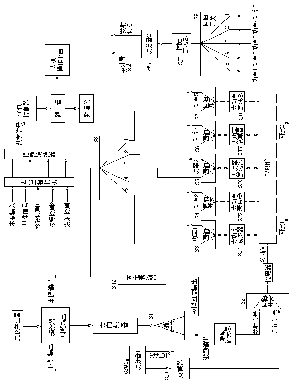
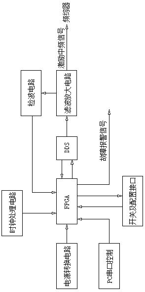
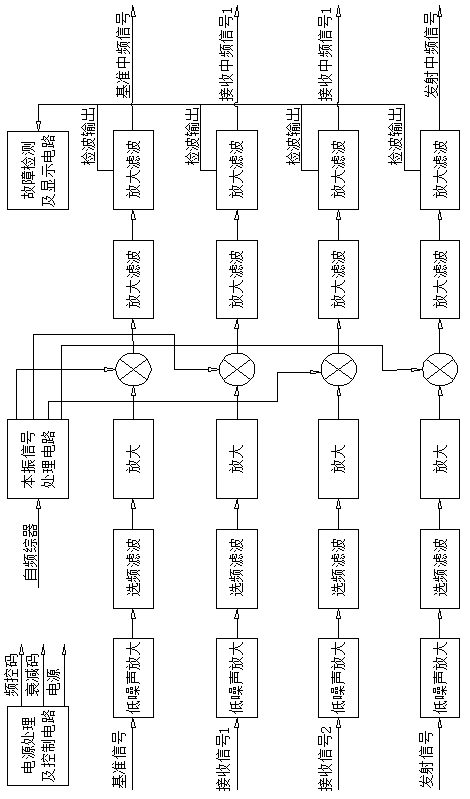
[0025] The implementation of this automatic T / R component testing system will be described in further detail below in conjunction with the accompanying drawings (see Figure 1-7 ):

[0026] An automatic T / R component test system, which includes a frequency synthesizer, a waveform generator, a four-in-one receiver, a communication controller, an analog-to-digital converter, a directional coupler, a coaxial switch, a power divider, a router, a large Power attenuator, power module, ventilation and cooling system, man-machine interface, independent software;

[0027] The waveform generator is a direct digital frequency synthesizer DDS, which generates intermediate frequency test signals and excitation signals, and outputs them to the frequency synthesizer after filtering and amplifying;

[0028] The frequency synthesizer includes a clock signal source, a local oscillator signal source, and an excitation signal source; the clock signal source provides a working clock of 15MHz for ...


PUM


Abstract

The invention relates to an automatic test system of T / R (Transmitter and Receiver) assemblies, and belongs to the technical field of radar detection devices. The system comprises a frequency synthesizer, a waveform generator, a four-in-one receiver, a communication controller, an autonomous software, and the like. The waveform generator is a direct digital synthesizer DDS. A clock signal source of the frequency synthesizer provides a working clock of 15MHz for the waveform generator, the communication controller, and an analog-to-digital converter. A local oscillator signal source provides local oscillator signals of the four-in-one receiver. An excitation signal source is used for providing an excitation signal and an analog echo signal for a tested T / R assembly through a through end ofa directional coupler and coaxial switches S1-S9. The excitation signal source provides a test signal for the tested T / R assembly through a coupling end of the directional coupler and a first power divider, and provides a reference signal for the system for system calibration. According to the automatic test system of the T / R assembly, switching of all channels and frequency points, data storage,calculation, and correction value writing can be automatically completed; human intervention is reduced; occupied instruments are few; the test is high in quality and efficiency; and the operate and maintain are convenient to be performed.

Description

technical field [0001] The invention relates to an automatic T / R component testing system, which belongs to the technical field of radar detection equipment. Background technique [0002] The T / R component is an indispensable core component of phased array radar, and its performance directly affects the working quality of the radar transceiver system. As the core component of the radar, the T / R component has a lot of performance indicators that must be checked and accepted. The test instruments involved in traditional testing of T / R component performance indicators include: power supply modules, spectrum analyzers, pulse vector network analyzers, signal sources, pulse generators, power meters, and computers; not only occupy a lot of instrumentation resources, but also these When the test instrument is used, it is necessary to manually calibrate the channel, set the parameters, switch the measured channel, calculate the correction value, write the correction value and record...

Claims


Application Information

Patent Timeline
Patent Type & Authority Applications(China)
IPC IPC(8): H04B17/11H04B17/15H04B17/21H04B17/29H04B17/00
CPCH04B17/0085H04B17/11H04B17/15H04B17/21H04B17/29
Inventor 袁君袁毛李松兰邓哲
Owner JINGZHOU NANHU MACHINERY CO LTD
Learn More