
Automatic intercepting filtering pond, and intercepting filtering device, system and method

A filter tank, automatic technology, applied in the field of interception filter device, automatic interception filter tank, sewage diversion, municipal rainwater, which can solve the problems of inconvenient cleaning, urban waterlogging, affecting the speed of flood discharge, etc.

Inactive Publication Date: 2019-02-22
WUHAN SHENGYU DRAINING SYST
View PDF3 Cites 3 Cited by
  • Summary
  • Abstract
  • Description
  • Claims
  • Application Information

AI Technical Summary

Problems solved by technology

At present, most of the rainwater is treated by filter screen, and the rainwater is pre-treated by simple filtration. However, this method of filter screen filtration will bring many problems, such as the filter screen may be blocked, hindering the discharge of rainwater and causing urban waterlogging , the floating objects are not collected after being intercepted, so it is very inconvenient to clean up, and this method is single, it can only remove the floating objects, but cannot remove the particles in the rainwater
[0004] The Chinese invention patent application with the publication number CN107601628A discloses a deformable particle separator, an online treatment tank and an online treatment system. Sedimentation treatment is carried out, but when there is a large amount of rainfall, a large amount of rainwater must flow through the buoyancy tank, overflow tank, and overflow wall to be discharged. This series of structures hinders the water flow and affects the speed of flood discharge. Therefore, it is necessary to develop An on-line treatment pool and its control method and rainwater treatment system that can not only perform deep filtration treatment on initial rainwater, but also quickly discharge flood when the rainfall is large

Method used


Image

  • Automatic intercepting filtering pond, and intercepting filtering device, system and method
  • Automatic intercepting filtering pond, and intercepting filtering device, system and method
  • Automatic intercepting filtering pond, and intercepting filtering device, system and method

Examples


Embodiment 1

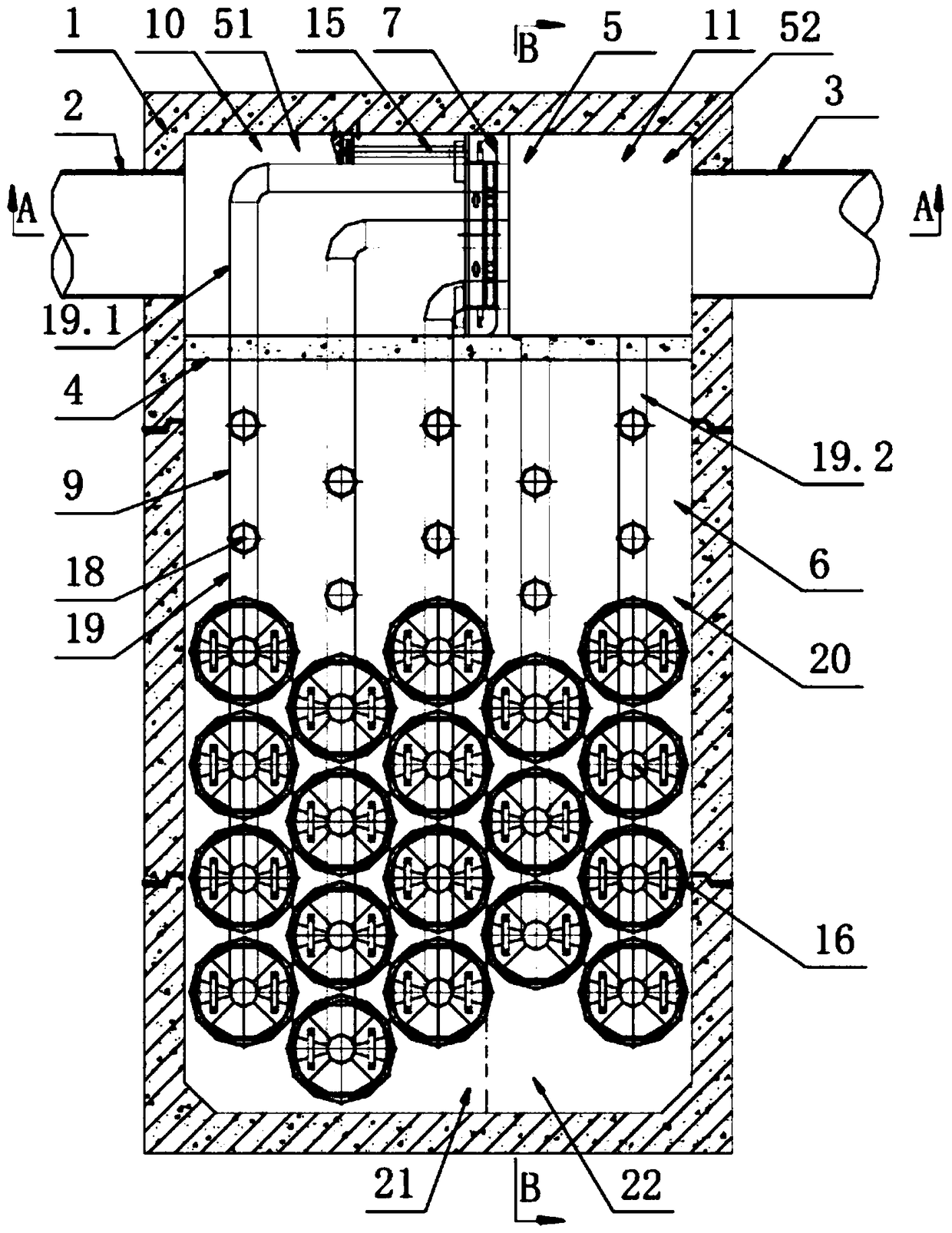
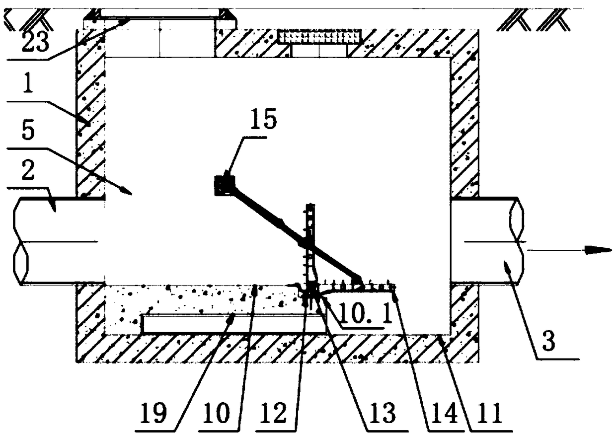
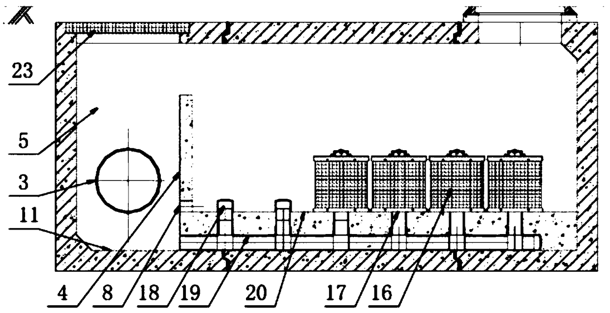
[0109] Such as Figure 1-3 As shown, the present embodiment provides an automatic interception filter tank with a hydraulic switch, including a tank body 1 and a water inlet 2 and a water outlet 3 which are oppositely arranged at the front and rear ends of the tank body 1, and also includes a water outlet installed in the tank body 1 along the water flow. The retaining wall 4 arranged in the direction, the retaining wall 4 is connected with the front and rear ends and the bottom of the pool body 1, and the retaining wall 4 divides the pool body 1 into a water passage corridor 5 and a filtration treatment area 6, and the water passage corridor 5 is provided with a vertical A hydraulic switch in the direction of water flow (the hydraulic switch can be a hydraulic down-opening weir gate, an electric gate or a hydraulic rotary weir gate, in this embodiment it is a hydraulic rotary weir gate 7), and the hydraulic switch divides the water passageway into 5 into a first zone 51 and a...

Embodiment 2

[0117] On the basis of Embodiment 1, the automatic retention filter tank of this embodiment also includes a control unit and a detection device for detecting water quality and / or water level and / or time and / or flow, and the detection device is arranged in the first zone 51, And the input end of the control unit is connected with the output end of the detection device, the output end of the control unit is connected with the hydraulic switch (hydraulic rotary weir gate 7), and the control unit is used to control the switch of the hydraulic switch according to the detection value detected by the detection device. The detection device in this embodiment is a liquid level sensor or a water quality sensor.

[0118] The above-mentioned automatic interception filter tank control method with a hydraulic switch, the steps are:

[0119] Setting: For the liquid level sensor, the warning water level H1 and the dry flow water level H2 are set in the control unit; for the water quality sens...

Embodiment 3

[0126] Such as Figure 4-5 , the present embodiment provides a interception filtration treatment device, comprising the automatic interception filter tank and the particle separation device of the above-mentioned embodiment 1 or 2, the particle separation device is located at the upstream of the automatic retention filter tank, so that the water flow enters the automatic retention filter after passing through the particle separation device in the pool.

[0127] The particle separation device includes the well body 101 of the intercepting well, the front water inlet 102 and the front water outlet 103 at the front and rear ends of the well body, and at least one front retaining wall. Between, and the top of the front retaining wall is not higher than the lowest water intake position of the front water inlet 102, the front retaining wall divides the well body 101 into several partition areas.

[0128] In the present embodiment, the front retaining wall has two sides, which are t...


PUM


Abstract

The invention discloses an automatic intercepting filtering pond, which comprises a pond body (1), a retaining wall (4), an automatic switch, a particle filtering device and a drainage device (9). A water inlet (2) and a water outlet (3) are formed in the pond body (1), the retaining wall (4) is arranged in the pond body (1) and divides the pond body (1) into a water passing corridor (5) and a filtering treating area (6), and the water inlet (2) and the water outlet (3) are located in the side wall, where the water passing corridor (5) is located, of the pond body (1); the automatic switch isarranged in the water passing corridor (5) to control a water flow in the water passing corridor (5) and divides the water passing corridor (5) into a first area (51) and a second area (52), the waterinlet (2) communicates with the first area (51), the water outlet (3) communicates with the second area (52), and the automatic switch comprises a separating wall (12) and one or more automatic switch bodies controlling the communicating state of the first area (51) and the second area (52); and the particle filtering device communicates with the drainage device and is arranged in the filtering treating area (6), wherein a water feeding hole (8) is formed in the part, at the first area (51), of the retaining wall (4) and can communicate with the filtering treating area (6) and the first area(51), and the drainage device (9) can communicate with the filtering treating area (6) and the second area (52).

Description

technical field [0001] The invention relates to the diversion of municipal rainwater and sewage, in particular to an automatic interception filter tank, an interception filter device, a system and a method, and belongs to the technical field of municipal water supply and drainage. Background technique [0002] Non-point source pollution, also known as non-point source pollution, is mainly composed of soil sediment particles, nutrients such as nitrogen and phosphorus, pesticides, and various atmospheric particles, which enter water, soil, or the atmosphere through surface runoff, soil erosion, and farmland drainage. . Its randomness, universality, hysteresis, ambiguity, latentness and other characteristics increase the difficulty of corresponding research, governance and management policy formulation. After the transformation of urban rain and sewage diversion, non-point source pollution is an urgent problem to be solved. If the particulate matter and floating matter in the ...

Claims


Application Information

Patent Timeline
Patent Type & Authority Applications(China)
IPC IPC(8): B01D29/33B01D29/52B01D29/60B01D37/04E03F1/00E03F5/14
CPCB01D29/52B01D29/33B01D29/60B01D29/605B01D37/04B01D37/045E03F1/00E03F5/14
Inventor 周超李习洪
Owner WUHAN SHENGYU DRAINING SYST
Learn More