Laser auxiliary electric jetting in-situ printing manufacturing method

A printing manufacturing and laser-assisted technology, which is applied in the direction of additive manufacturing, manufacturing tools, and manufacturing auxiliary devices, can solve problems such as limited spatial layout accuracy, weak bonding performance between functional units and substrates, and excessively large manufacturing scale of functional units. Effects of sensitivity and stability, reduced feature size, improved dimensional accuracy and bond strength

Active Publication Date: 2019-02-22
DALIAN UNIV OF TECH
View PDF8 Cites 4 Cited by
  • Summary
  • Abstract
  • Description
  • Claims
  • Application Information

AI Technical Summary

Problems solved by technology

Although these methods are simple and practical, they still have shortcomings such as limited accuracy of spatial layout,

Method used


Image

  • Laser auxiliary electric jetting in-situ printing manufacturing method
  • Laser auxiliary electric jetting in-situ printing manufacturing method

Examples


Embodiment Construction

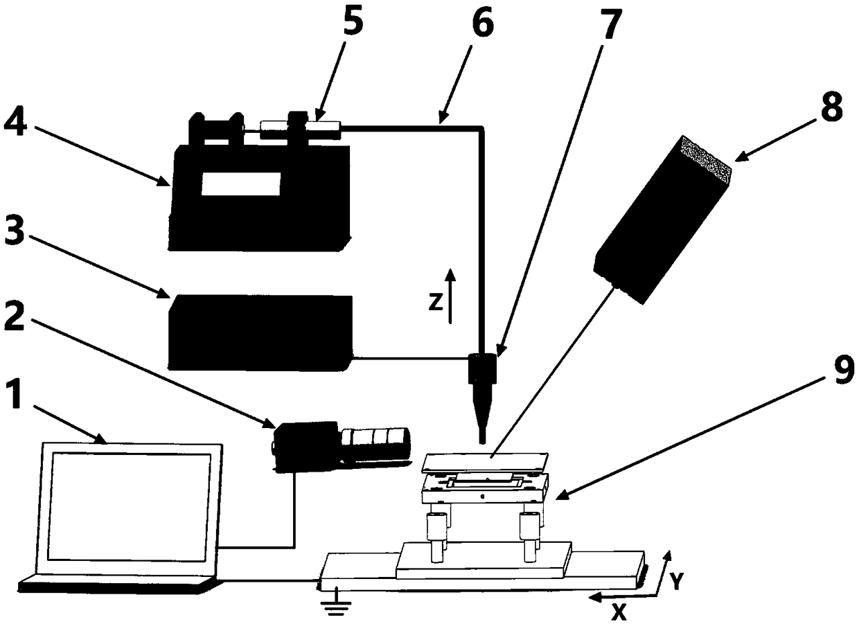
[0026] The present invention is further described in combination with technical solutions and drawings. The laser-assisted electrospray in-situ printing manufacturing device of the embodiment includes an electrospray printing module, a laser in-situ functionalization processing module, and the like.

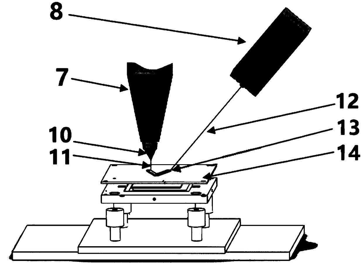
[0027] The precision syringe 5 is installed on the micro-injection pump 4, and "ZnO suspension ink" is housed inside. The injection needle 7 is connected to the precision syringe 5 through the conduit 6, the high-voltage power supply 3 outputs 1200V, the positive output terminal is connected to the injection needle 7, and the negative electrode is connected to the printing plate 14. The needle 7 flows out and under the action of the electric field, a stable Taylor cone 10 is formed at the needle outlet, and a stable fine jet 11 is ejected to print on the substrate, and the X / Y axis motion platform drives the printing plate 14 according to the predetermined The motion track moves ...


PUM

PropertyMeasurementUnit
Spot diameteraaaaaaaaaa

Abstract

The invention belongs to the technical field of advanced manufacturing, and provides a laser auxiliary electric jetting in-situ printing manufacturing method. A functional material ink flows out froma spraying needle port under the action of pressure, and due to the action of the electrohydrodynamics effect, a stable Taylor cone is formed to jet out stable fine jet flow to a base body to form a printing layer. Meanwhile, a laser energy device is used for carrying out composite processing on the printing layer, emitting laser beams and irradiating the printing layer according to printing tracks, and high-temperature curing, crystallization and other functional processing on a printing structure can be synchronously realized in situ. According to the method, functional structures and devices are directly realized on the base body in situ, the problem of secondary positioning errors of transferring, gluing, splicing and the like in a traditional method is eliminated, the problems that binding force is weak, and sensitivity is low due to a gluing process are avoided, and the feature size of a functional unit can be reduced by means of the high-resolution printing advantage of electricjetting; and the size precision and the bonding strength of a printing unit structure are improved, so that the sensitivity and the stability of the devices are improved.

Description

technical field [0001] The invention belongs to the field of advanced manufacturing technology, and in particular relates to a laser-assisted electrospray in-situ printing manufacturing method. Background technique [0002] With the integration and deep integration of advanced manufacturing technology, information technology and intelligent technology, high-end intelligent equipment continues to develop in the direction of modularization, integration, and intelligence. Therefore, intelligent equipment needs to integrate more sensors, drives, controls, etc. Functional structural units to meet specific functional requirements. [0003] In the fields of aviation, aerospace, medical treatment, and microelectronics, there are a large number of intelligent equipment components that need to integrate multiple discrete functional structural units to realize specific comprehensive functions. For example, deformed-wing aircraft can complete the deformation of the wing by integrating ...

Claims


Application Information

Patent Timeline
IPC IPC(8): B29C64/135B29C64/20B29C64/209B29C64/268B29C64/321B29C64/393B33Y30/00B33Y40/00B33Y50/02
CPCB29C64/135B29C64/20B29C64/209B29C64/268B29C64/321B29C64/393B33Y30/00B33Y40/00B33Y50/02
Inventor 王大志赵奎鹏姜重阳钱江红韦运龙周鹏李经国王柱杜致远任同群梁军生
Owner DALIAN UNIV OF TECH
Why Eureka
Try Eureka