
Ocean network system

A network system and ocean-going technology, applied in the field of ocean-going network systems, can solve the problems of inability to pass through walls, poor network signals, and expensive charges, and achieve the effects of maintaining stable network signal connections, high signal transmission speed, and reducing the required time.

Active Publication Date: 2019-02-22
TAIZHOU KEPUNI COMM EQUIP CO LTD
View PDF4 Cites 0 Cited by
  • Summary
  • Abstract
  • Description
  • Claims
  • Application Information

AI Technical Summary

Problems solved by technology

[0002] Satellite antennas for ships are relatively popular. The disadvantage is that they cannot receive satellite TV signals when they are far away from the shore. They can access the Internet through satellite signals, but the network speed is extremely slow and the charges are expensive. In addition, it is difficult for seafarers who have traveled at sea for a long time to communicate with land normally. connect,
[0003] At present, the ship-to-shore wireless network shore station can already realize the wireless network connection with offshore ships, but there are problems such as short receiving distance of network signal, low upper limit of network speed, poor network signal when the distance is slightly farther, and low security.
But because of its fatal shortcoming - unable to pass through walls, its research lags far behind the current popular WIFI wireless transmission technology
[0006] However, on the vast ocean, except for the limited field of view caused by the curvature of the earth, there are almost no objects that can affect the propagation of light. Therefore, the value of visible light network technology in ocean networks is worth studying, and now with the People in the ocean have an increasing demand for traffic, and LIFI may become our better choice in the future

Method used


Image

  • Ocean network system
  • Ocean network system
  • Ocean network system

Examples


Embodiment 1

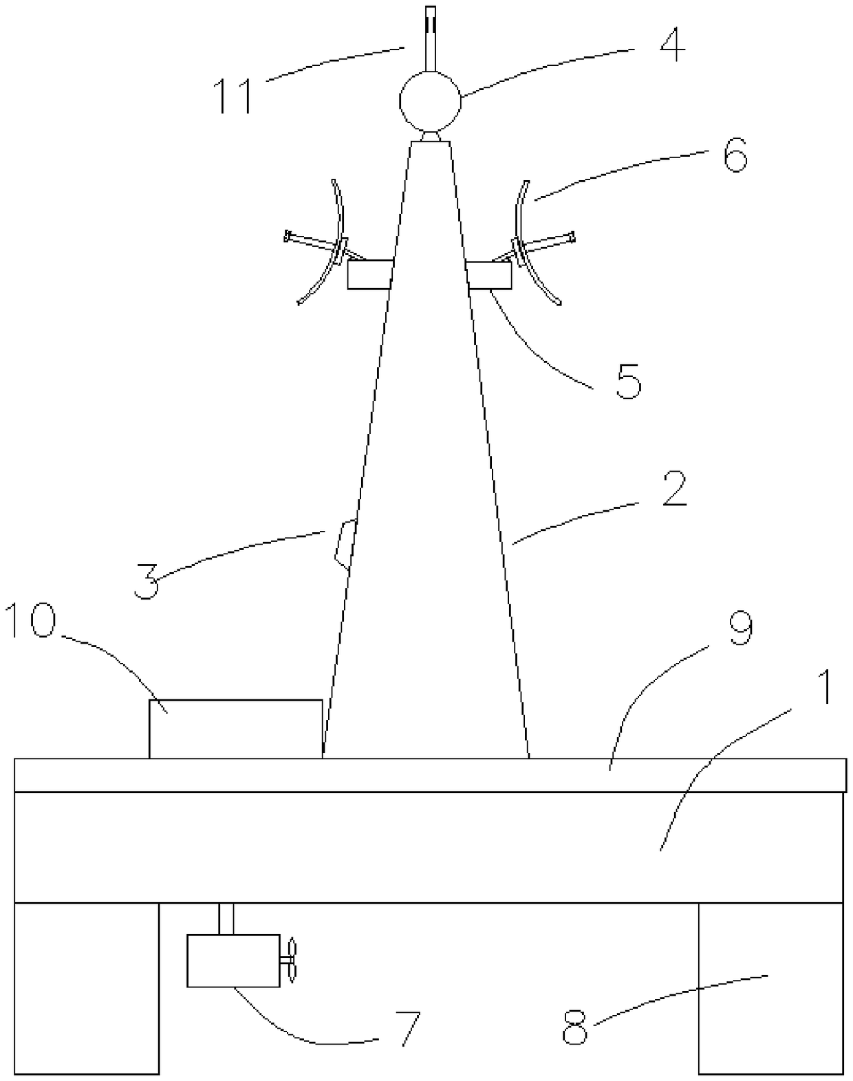
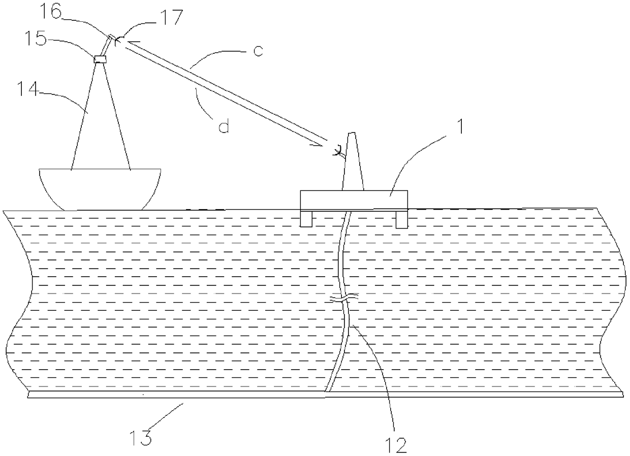
[0043] Such as Figure 1-3 As shown, an ocean-going network system includes a shipborne signal system, a signal floating island and a remote control terminal;

[0044] The shipborne signal system includes a base 14 fixed to the hull, a shipborne GPS positioning device 15 installed on the base, a shipborne signal alignment device 16 installed on the upper part of the base, and a shipborne signal alignment device 的 Shipboard signal transceiver 17;

[0045] The signal floating island includes an island base 1, a solar power supply system installed on the island base, a signal rack installed at the center of the island base 2, an island-based GPS positioning device 3 installed on the signal rack, and an island-based GPS positioning device installed on the top of the signal rack. Request signal receiving device 4, island-based signal alignment device 5 installed on the upper side of signal rack 2, island-based signal transceiving device 6 installed on the island-based signal alignment d...

Embodiment 2

[0060] The network operation steps of the ocean-going network system are:

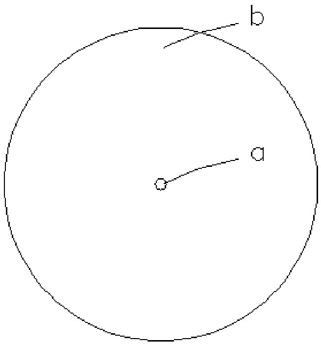
[0061] S1) The shipborne signal alignment device 16 obtains its own positioning from the GPS positioning device 15, and finds the preset coordinate position of the nearby signal floating island from the electronic map, and calculates the shipborne signal according to the distance, azimuth, and elevation difference between the two The adjustment position required by the signal transceiving device enables the orientation of the shipborne signal transceiving device to be adjusted, and the request signal is scanned and transmitted to the preset coordinate position a and the nearby area b. The request signal includes the ship’s call sign, ship’s name, MMSI, GPS coordinates, the deviation value of the shipborne signal transceiver device and the shipborne GPS positioning device;

[0062] S2) After receiving the request signal, the request signal receiving device 4 authenticates the request signal. After passing th...

Embodiment 3

[0067] Through the camera and temperature sensor, the remote control terminal can grasp the marine weather and hydrological information, as well as the situation of passing ships, and provide detailed data for the marine management department.


PUM


Abstract

The invention relates to an ocean network system. The ocean network system comprises a ship-borne signal system, a signal floating island and a remote control terminal, wherein the ship-borne signal system comprises a base, a ship-borne GPS positioning device, a ship-borne signal aligning device, and a signal-borne signal sending and receiving device; and the signal floating island comprises an island base, a solar power supply system, a signal frame, an island base GPS positioning device, a request signal receiving device, an island base signal aligning device, an island base signal sending and receiving device and a power device. The island base signal aligning device of the ocean network system receives the request signal and then authenticates the request signal; the request signal receiving device calculates according to the request signal to obtain the orientation of the ship-borne signal sending and receiving device; the regulating island base signal aligning device enables theisland base signal sending and receiving device to align to the ship-borne signal sending and receiving device, and sends out a down link signal to the ship-borne signal sending and receiving device;and after receiving the down link signal, the ship-borne signal sending and receiving device sends an up link signal to the island base signal sending and receiving device, so that high-quality network signal connection can be realized after abutting is successful.

Description

Technical field [0001] The invention belongs to the field of ocean networks, and specifically relates to an ocean-going network system. Background technique [0002] Marine satellite antennas have become more popular. The disadvantage is that they cannot receive satellite TV signals when they are far away from the shore. You can access the Internet through satellite signals. However, the Internet speed is extremely slow and the charges are expensive. In addition, it is difficult for crew members who travel at sea for a long time to communicate with land. contact, [0003] At present, the ship-to-shore wireless network shore station can already realize the wireless network connection with offshore ships, but the problems are that the network signal receiving distance is short, the upper limit of the network speed is low, the network signal is poor when the distance is slightly longer, and the security is low. [0004] Lifi, the visible optical network technology, is a wireless transm...

Claims


Application Information

Patent Timeline
Patent Type & Authority Applications(China)
IPC IPC(8): B63B49/00H04W4/024H04W4/42
CPCH04W4/024H04W4/42B63B49/00
Inventor 崔小飞
Owner TAIZHOU KEPUNI COMM EQUIP CO LTD
Learn More