
A kind of infrared transparent ceramic material and preparation method thereof

A transparent ceramic and infrared technology, applied in luminescent materials, chemical instruments and methods, etc., can solve the problems of harsh service environment of infrared windows/fairings, increased aerodynamic force and aerodynamic heat, etc. Growth rate, effect of grain size reduction

Active Publication Date: 2020-07-17
NORTHEASTERN UNIV LIAONING
View PDF7 Cites 0 Cited by
  • Summary
  • Abstract
  • Description
  • Claims
  • Application Information

AI Technical Summary

Problems solved by technology

[0004] However, due to the continuous improvement of the attack rate requirements, the service environment of the infrared window / dome is getting worse and worse. During the ultra-high-speed flight of the missile, the aerodynamic force and aerodynamic heat generated by the friction between the front end of the missile and the atmosphere also increase sharply. The shield is in such a complex thermal mixing state, and further improvement and stability of its optical and mechanical properties have become the main challenge for infrared transparent ceramics.

Method used


Image

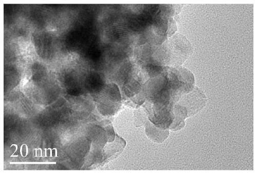
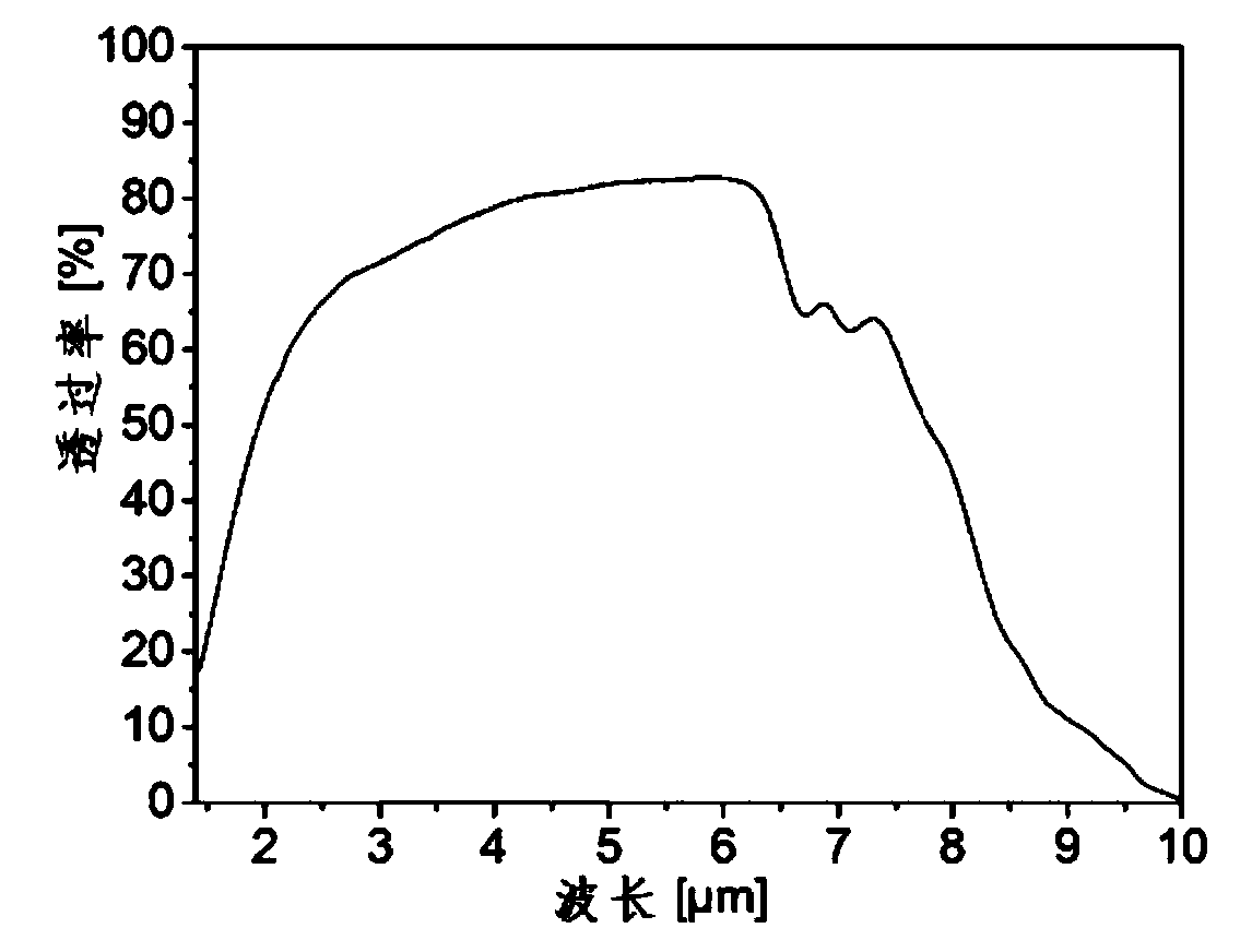
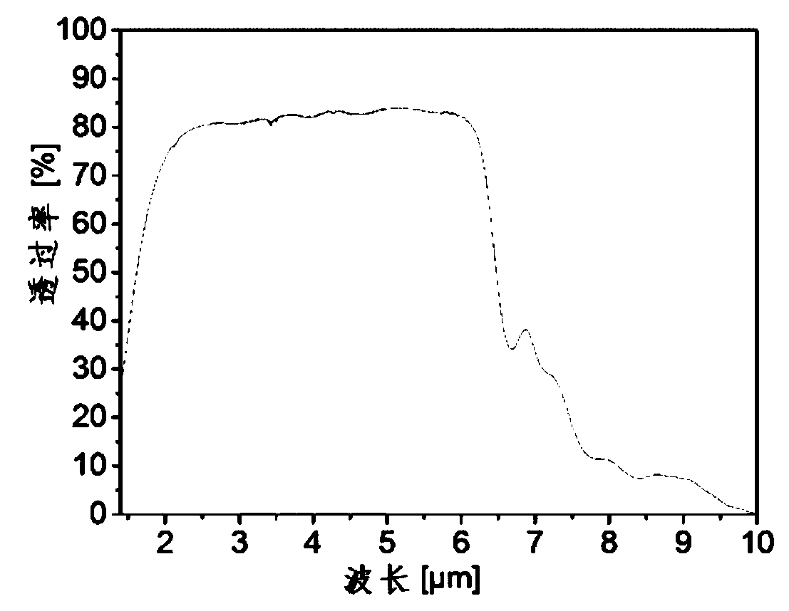
  • A kind of infrared transparent ceramic material and preparation method thereof
  • A kind of infrared transparent ceramic material and preparation method thereof
  • A kind of infrared transparent ceramic material and preparation method thereof

Examples


Embodiment 1-4

[0097] Examples 1-4 use the above-mentioned solid-phase method to synthesize the above-mentioned nanocomposite powder, and the specific steps are similar to the above-mentioned steps, which are mainly realized by adjusting the process parameter conditions of each step. Embodiments 1-4 adopt the above-mentioned solid-phase method to synthesize the process conditions of the above-mentioned nanocomposite powder specifically as shown in Table 1 below:

[0098] Table 1: The technological parameter condition of embodiment 1-4

[0099]

Embodiment 5-8

[0101] Examples 5-8 use the above-mentioned co-precipitation method to synthesize the above-mentioned nanocomposite powder, and the specific steps are similar to the above-mentioned steps, which are mainly realized by adjusting the process parameter conditions of each step. Examples 5-8 The process conditions for synthesizing the above-mentioned nanocomposite powders by the above-mentioned co-precipitation method are specifically shown in Table 2 below:

[0102] Table 2: The technological parameter condition of embodiment 5-8

[0103]

Embodiment 9-12

[0105] Examples 9-12 use the above-mentioned homogeneous precipitation method to synthesize the above-mentioned nanocomposite powder, and the specific steps are similar to the above-mentioned steps, which are mainly realized by adjusting the process parameter conditions of each step. Embodiments 9-12 The process conditions for synthesizing the above-mentioned nanocomposite powder by the above-mentioned uniform precipitation method are specifically shown in Table 3 below:

[0106] Table 3: The technological parameter condition of embodiment 9-12

[0107]

[0108]


PUM

PropertyMeasurementUnit
particle sizeaaaaaaaaaa
hardnessaaaaaaaaaa
particle diameteraaaaaaaaaa

Abstract

The invention relates to an infrared transparent ceramic material and a preparation method thereof, wherein the general composition formula of the infrared transparent ceramic material is Y 2 O 3 ‑MgO‑Gd 2 O 3 , using Y 2 O 3 of nanopowder, MgO nanopowder and Gd 2 O 3 Nanocomposite powder composed of nanopowder is fired. Y 2 O 3 The volume ratio of nanopowder and MgO nanopowder is 1:1, Gd 2 O 3 The percentage of nanopowder in the total molar amount of nanocomposite powder is 0.01 to 18%. The infrared transparent ceramic material in the present invention has Gd 2 O 3 It has extremely high density and mechanical strength, and at the same time due to Gd during the sintering process 2 O 3 The addition of can inhibit the grain boundary diffusion speed, reduce the grain growth rate, reduce the grain size of ceramic materials, and achieve the purpose of fine grain strengthening. The transmittance of transparent ceramic materials is not affected and the mechanical properties are further improved. Meet higher performance requirements for infrared window materials.

Description

technical field [0001] The invention belongs to the technical field of transparent ceramic materials, and in particular relates to an infrared transparent ceramic material and a preparation method thereof. Background technique [0002] Aiming at the development trend of high Mach number missiles in the future and the technical challenges faced by infrared window materials, several common infrared window materials are compared and analyzed. At present, 3-5μm medium-wave infrared detectors are widely used in infrared countermeasures, remote sensing, infrared guidance and detection, high-energy laser weapons, thermal imaging cameras, night vision devices, flame gas detectors, environmental monitoring, and space due to their high spatial and temperature resolution. It has been widely used in many fields such as communication. Y 2 o 3 The emissivity has the smallest change with wavelength, and has the lowest high-temperature infrared radiation coefficient at the same temperatu...

Claims


Application Information

Patent Timeline
Patent Type & Authority Patents(China)
IPC IPC(8): C04B35/505C04B35/622C04B35/626C04B35/645C09K11/77
CPCC04B35/505C04B35/622C04B35/62605C04B35/645C04B2235/3206C04B2235/3224C04B2235/602C04B2235/6567C04B2235/6581C04B2235/6583C04B2235/662C04B2235/666C04B2235/9653C09K11/7766
Inventor 李晓东付仲超张牧孙旭东
Owner NORTHEASTERN UNIV LIAONING
Learn More