Building with precast reinforced concrete supports

A technology of concrete support and reinforced concrete, which is applied in the direction of buildings, building components, building structures, etc., and can solve the problems of limited connection space of reinforcement bars in two-way stressed cavity floors, cumbersome connection of reinforcement bars, and large components.

Inactive Publication Date: 2019-02-22
HUNAN BDF ENERGY SAVING TECH +2
View PDF6 Cites 34 Cited by
  • Summary
  • Abstract
  • Description
  • Claims
  • Application Information

AI Technical Summary

Problems solved by technology

[0004] In order to promote the development of housing industrialization in China, the inventor applied for ZL201620408935.8 "passive building energy-saving integrated system", which extended the cast-in-place concrete hollow floor to the field of prefabricated buildings through creation and transformation, and solved the overall problem of prefabricated building structures. problems such as poor performance, long-span unidentified beams, oversized components, industrialization of components, controllability of building quality, work efficiency and environmental protection; although these inventions have laid the foundation for the industrialization of housing in my country, there are still long strips of prefabricated assemblies. The unidirectionality of the stress on the cavity slab, the cracks in the gap when two prefabricated cavity slabs are put together, and the limited connection space of the transverse reinforcement of the two-way stressed cavity floor, etc.
[0005] In order to overcome the difficulty of low assembly rate of reinforced concrete prefabricated building structures, the inventor applied for 201710951186.2 "a prefabricated building structure", which increased the assembly rate from less than 40% to more than 70%, passed the national test and acceptance, and ensured structural safety Strong and economical, it has played an active role in the government's promotion of prefabricated buildings; however, the beams, columns, and floor nodes are all in the cast-in-place state. Although the structure is safe, it requires a large number of temporary supports to support the beams, columns, and floor components. There are many steel bar joints at the intersections of beams and beams, and beams and columns, and the steel bar connections are cumbersome and expensive
[0006] At present, there are still many technical problems unresolved in the prefabricated buildings of reinforced concrete frame structure, resulting in high construction costs and hindered promotion; therefore, the inventors have tested and verified the beams, columns, The cast-in-place concrete joint area of ​​the floor slab is creatively changed to a "prefabricated reinforced concrete support body" to enhance the ability of shear force and punching resistance, and the post-cast concrete column and beam joints are scattered in the middle of the column and prefabricated On the assembly end of the main beam set on the rhombus-shaped or triangular water chestnut outside the reinforced concrete support; There are no steel joints at the joints of beams and columns, which greatly reduces the number of supporting rods and further speeds up the assembly speed, improves the quality of the assembly, and reduces the cost of the project; realizes the overall prefabricated building with strong columns and weak beams and then pouring the flange laminated layer on the floor Structural new technology; it is a major breakthrough in the new technology system of prefabricated building with reinforced concrete frame structure, and has become an urgent need for innovation in the field of prefabricated building technology

Method used


Image

  • Building with precast reinforced concrete supports
  • Building with precast reinforced concrete supports
  • Building with precast reinforced concrete supports

Examples


Embodiment Construction

[0024] The invention will be further described below in conjunction with the accompanying drawings.

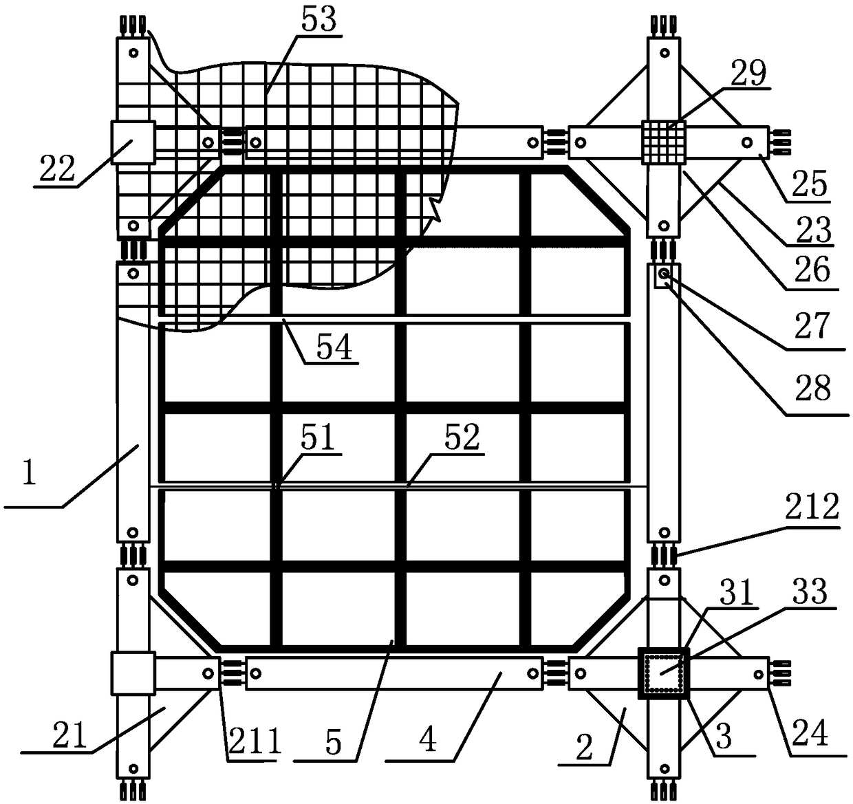
[0025] figure 1 It is a plane embodiment diagram of the frame structure of the present invention, during the implementation of the present invention;

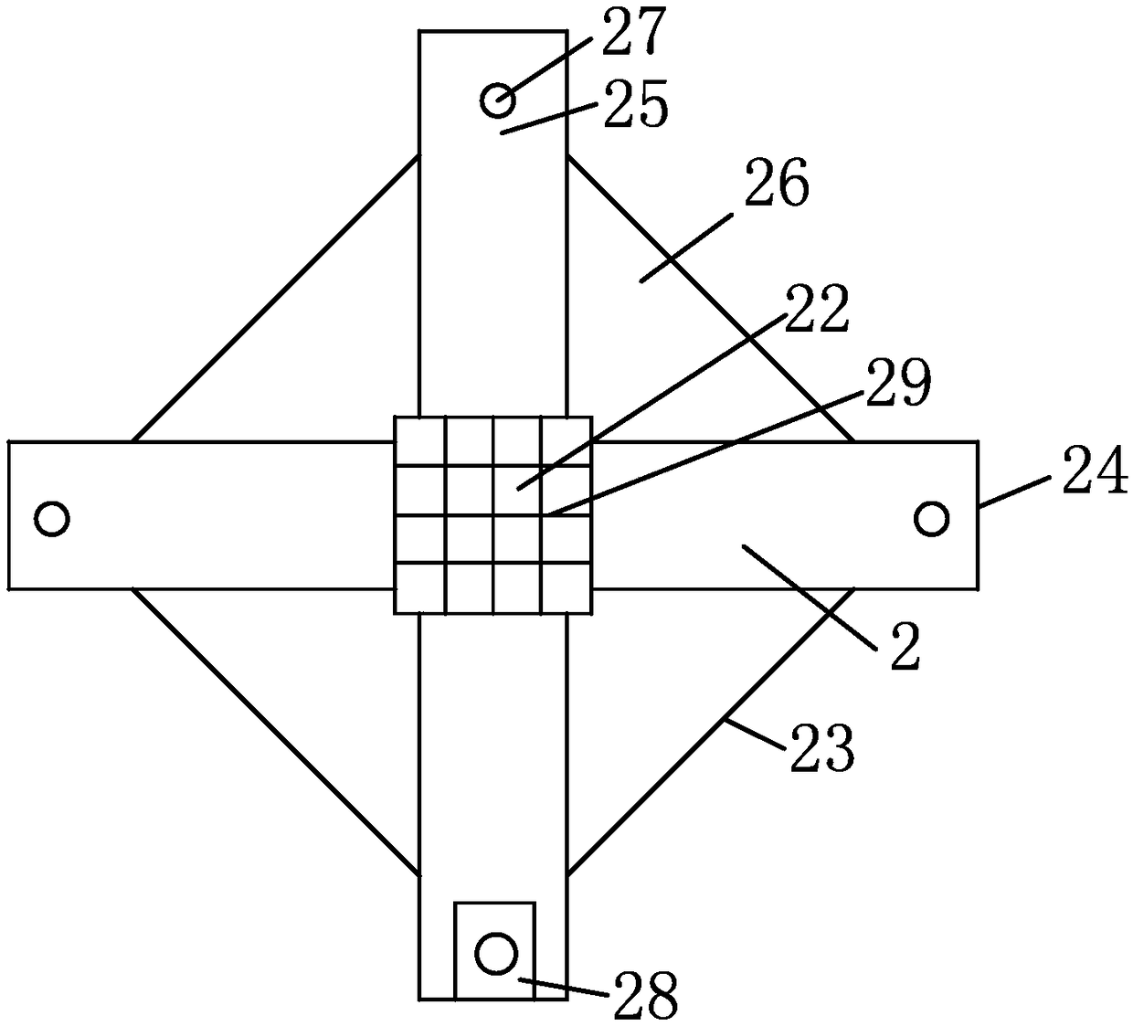
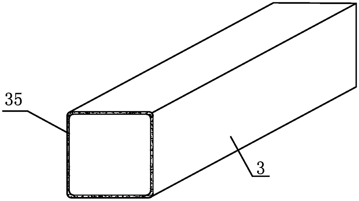
[0026] Step 1: Manufacture the prefabricated concrete column frame 3 of the specifications and models required by the frame structure 1, the diamond-shaped prefabricated reinforced concrete support body 2 or the triangular prefabricated reinforced concrete support body 21, the prefabricated main beam 4, the prefabricated stairs, and the cavity Floor 5 and column reinforcement 31; diamond-shaped prefabricated reinforced concrete support body 2 includes main beam assembly end 24, square column hole 22 in the middle of the support, rhombus side 23, water chestnut 25, reinforced concrete between beams 26, and bolt holes 27 , the main beam connecting steel plate 28, the main beam cross reinforcement 29 in the square column hole 22 ...


PUM


Abstract

The invention provides a building with precast reinforced concrete supports. The building is composed of the precast reinforced concrete convex supports, precast column frames, precast convex main beams, cavity floor components and connecting shallow seams among the cavity floor components. The building is characterized in that the precast reinforced concrete convex supports are each in a rhombicshape; rhombic convex support diagonal lines are constituent parts of the main beams; reserved column holes are formed in the centers of the convex supports, and longitudinal main beam reinforcing bars and transverse main beam reinforcing bars in the reserved column holes are crossed and have no reinforcing bar joint; the precast column frames are thin-wall frames, and steel wire nets are arrangedin the thin-wall frames; the cavity floor components are each shaped like a hexagon; each hexagonal cavity floor component is provided with two right-angle edges; longitudinal rib grooves and shallowconnecting seams are formed among the cavity floor components; the two ends of each precast main beam are provided with slopes or vertical grooved slopes; vertical bolt holes are reserved in the twoends of the main beams; concave grooves are reserved in the bottom surface of the two ends of the main beams; and steel plate connecting parts are assembled in the concave grooves.

Description

technical field [0001] The invention relates to a prefabricated building system technology, in particular to a building with prefabricated reinforced concrete supports; the invention belongs to the divisional application of 201711474917.5. Background technique [0002] In order to adjust the structure of the construction industry, improve the quality of construction, speed up construction, achieve energy conservation and environmental protection, and reduce project costs, the state has proposed to vigorously promote prefabricated buildings and specified specific implementation plans; Wall structure, steel structure and steel-concrete composite structure system are widely used, and the structural system and application field of my country's prefabricated building are clarified; however, the prefabricated building with long-span reinforced concrete frame structure has just started, and ordinary laminated floors are used. And the double T-slab floor technology leads to high cost ...

Claims


Application Information

Patent Timeline
Patent Type & Authority Applications(China)
IPC IPC(8): E04B1/21E04B5/14E04B5/48E04C3/20E04C3/34
CPCE04B1/21E04B5/14E04B5/48E04C3/20E04C3/34
Inventor 王海崴王本淼
Owner HUNAN BDF ENERGY SAVING TECH
Why Eureka
Try Eureka