Half-space beam-covered circularly polarized luneberg lens antenna

A Lumberg lens antenna, half-space technology, which is applied to antenna arrays that are energized separately, antenna combinations with different interactions, antennas, etc., which can solve the problems of edge beam gain reduction, low overall gain, and beam deformation gain. Achieving beamwidth, reduced feed count, high impedance, and high axial ratio bandwidth

Active Publication Date: 2019-02-22
UNIV OF ELECTRONICS SCI & TECH OF CHINA
View PDF6 Cites 11 Cited by
  • Summary
  • Abstract
  • Description
  • Claims
  • Application Information

AI Technical Summary

Problems solved by technology

Japan's Sumitomo Electric Industries Co., Ltd. foams the foamed plastic beads through the mold opening method in the patent CN101057370, but the process flow of this method is very complicated and the foaming uniformity is difficult to control, and the processing conditions are very high, resulting in unreasonable processing costs. Difficulty in control and mass production
American patent inventor Michael.P.Carpenter et al. disclosed in the patent No. US 6433936 B1 titled "Lens of Gradient Dielectric Constant and Methods of Production" that thermoplastic resin expansion beads (polystyrene, polyamide, etc.) were doped with ceramic materials (titanium dioxide, silicon dioxide, etc.) are filled into the mold, and heated to melt them together, and the dielectric constant of each spherical shell is controlled by adjusting the density of the foam molding and the ceramic content. Good practicability, but the process is relatively complicated, not suitable for mass production
DL.Runyon et al. have introduced in detail a kind of special drill bit that utilizes a quadratic curve to open a gradual tapered hole along the radial direction of the dielectric lens in U.S. Patent US 5,677,796 entitled "Lunebe

Method used


Image

  • Half-space beam-covered circularly polarized luneberg lens antenna
  • Half-space beam-covered circularly polarized luneberg lens antenna
  • Half-space beam-covered circularly polarized luneberg lens antenna

Examples


Embodiment Construction

[0028] specific implementation plan

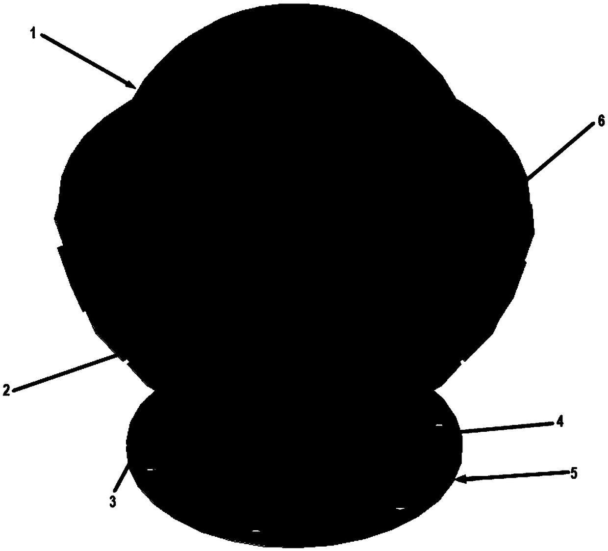
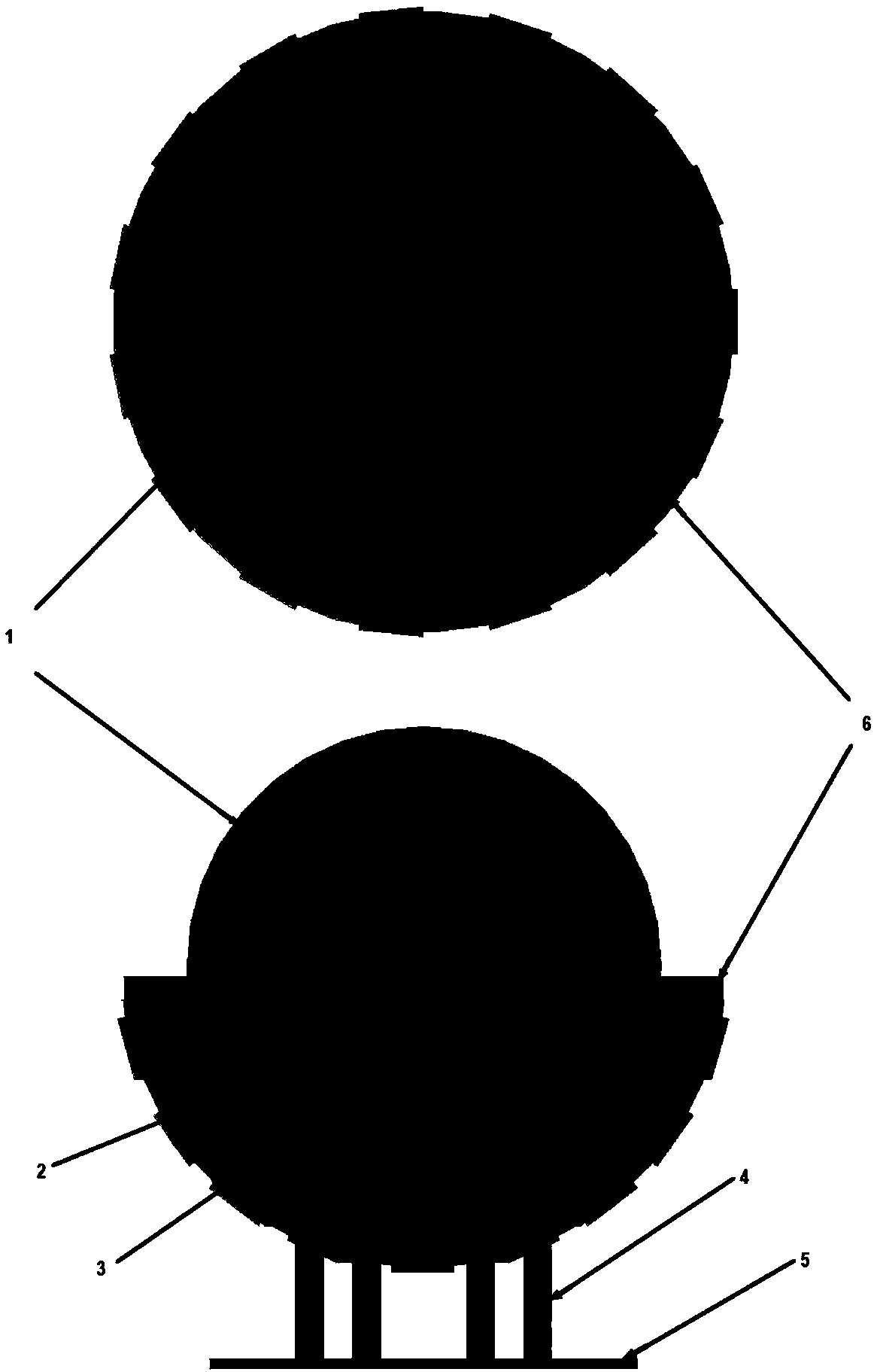
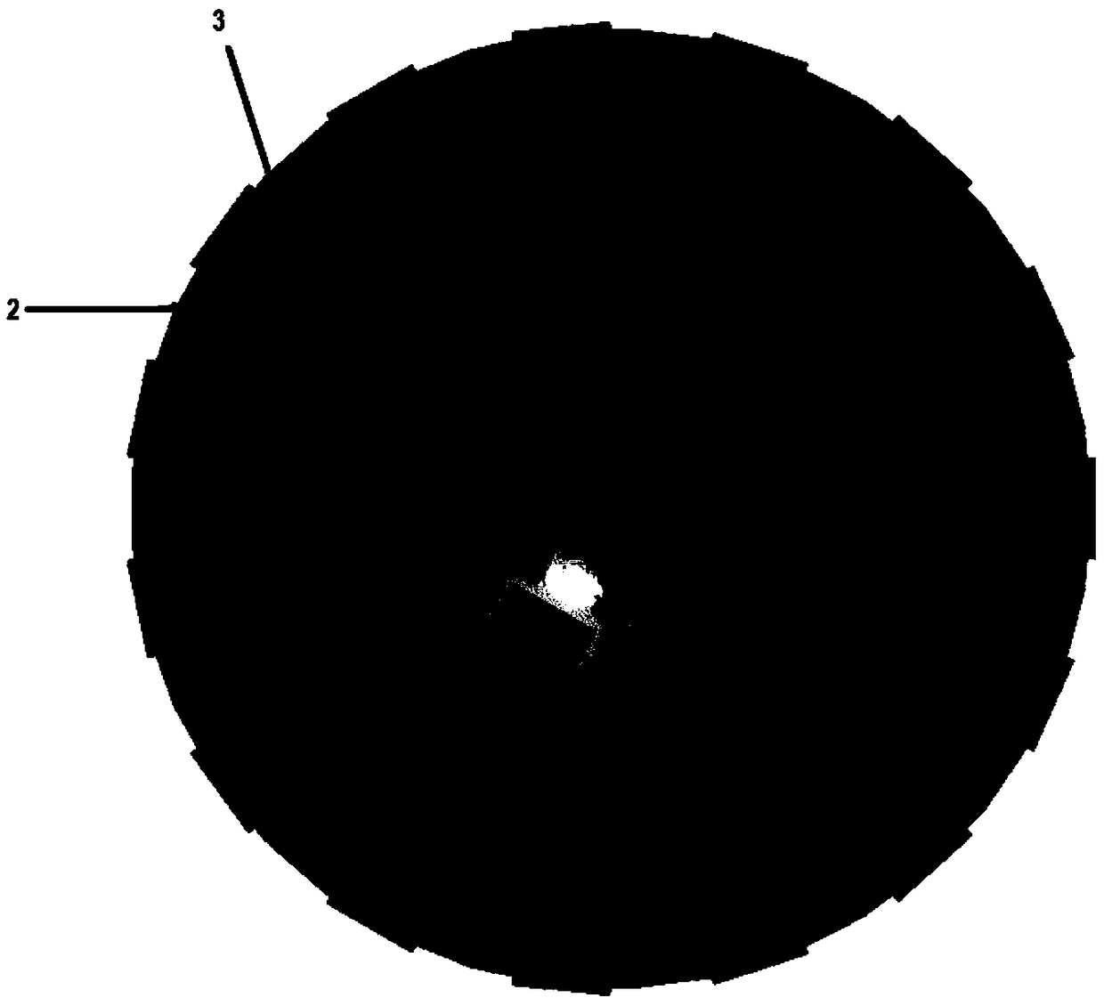
[0029] figure 1 and figure 2 The design structure of a circularly polarized Lunberg lens antenna covered by a half-space beam is exemplarily described. As shown in the figure, this structure includes a five-layer dielectric Lunber lens (1), a plexiglass fixing frame (2), a microstrip feed antenna (3), a support column (4), a fixing base (5), and a lens fixing Disc (6).

[0030] The microstrip feed antenna has wide lobe and low cross-polarization characteristics, which can effectively and uniformly illuminate the Lunberg lens, so that the Lunberg lens antenna has high aperture efficiency and has a small size, with a length and width of 13mm , which is less than half of the working wavelength, which is beneficial to reduce aperture shielding during large-angle scanning on the elevation plane and facilitates the arrangement of the feed source (3). 46 microstrip feed antennas (3) are arranged in a hemispherical shape along the focal point...


PUM

PropertyMeasurementUnit
Heightaaaaaaaaaa

Abstract

The invention discloses a half-space beam-covered circularly polarized luneberg lens antenna for large-scale multi-beam directional communication and half-space range beam scanning. The basic structure of the antenna consists of a spherical array formed by a plurality of circularly polarized microstrip feed source antennas, a layered dielectric lens processed by the 3D printing technology and a spherical organic glass fixing support. The lens antenna uses small circularly polarized microstrip antennas as feed source antennas which from a feed source array in a hemispherical non-uniform form, the feed source array is embedded in the fixing support made of organic glass, which reduces the aperture occlusion problem during large-area beam scanning, realizes beam scanning in a half-space range, and solves a series of design and processing problems encountered in the process of designing a luneberg lens antenna in the application of half-space beam coverage, contributes to application of the luneberg lens antenna to the usage scenarios and corresponding market requirements of large-scale multi-beam directional communication and half-space range beam scanning.

Description

technical field [0001] The invention belongs to the technical field of antennas, and relates to a Luneberg lens antenna, specifically a circularly polarized Luneberg lens antenna for multi-beam directional communication and half-space beam coverage of beam scanning, especially suitable for working in large-scale multi-beam Use cases for directional communication and half-space range beam scanning. Background technique [0002] Due to the urgent demand for multi-beam antennas in the fields of ship navigation, satellite communication, electronic countermeasures and target tracking, multi-beam antennas with high gain, narrow beam, low sidelobe, wide scanning angle, high-speed scanning and low manufacturing cost have been adopted. Focus. Based on the above requirements, the present invention designs a circularly polarized Lunberg lens antenna covered by half-space beams, which is especially suitable for use scenarios that work in large-scale multi-beam directional communication...

Claims


Application Information

Patent Timeline
IPC IPC(8): H01Q1/50H01Q15/02H01Q21/00H01Q21/06H01Q21/20H01Q21/29
CPCH01Q1/50H01Q15/02H01Q21/0006H01Q21/0087H01Q21/065H01Q21/20H01Q21/293
Inventor 杨仕文赵春雨屈世伟陈益凯黄明
Owner UNIV OF ELECTRONICS SCI & TECH OF CHINA
Why Eureka
Try Eureka