Method for machining signal transmission device, signal transmission device, and mobile terminal
A technology of signal transmission and processing method, applied in the field of communication, can solve problems such as poor mechanical properties and poor support of conductive layers
- Summary
- Abstract
- Description
- Claims
- Application Information
AI Technical Summary
Problems solved by technology
Method used
Image


Examples
Embodiment 1
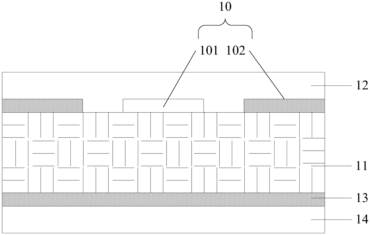
[0021] An embodiment of the present invention provides a signal transmission device, which may specifically include: a first conductive layer and a dielectric layer, wherein the first surface of the first conductive layer is connected to the dielectric layer; the dielectric layer is a fiber braided structure. In the embodiment of the present invention, the dielectric layer of the signal transmission device is a fiber braided structure. In practical applications, since the fiber braided structure has the characteristics of low dielectric constant and low loss tangent angle, the dielectric layer is a fiber braided structure. In the case of a braided structure, the dielectric layer is correspondingly characterized by low dielectric constant and low loss tangent. In this way, when the signal transmission device is used to transmit high-frequency signals, the transmission loss of the high-frequency signals can be reduced, and the integrity of the high-frequency signals can be impro...
Embodiment 2
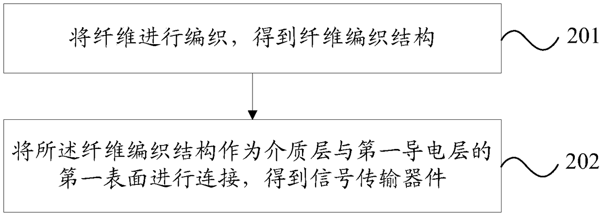
[0047] refer to figure 2 , which shows one of the step flow charts of an embodiment of a processing method of a signal transmission device according to the present invention, which may specifically include the following steps:
[0048] Step 201: Weaving the fibers to obtain a fiber weaving structure.
[0049] In the embodiment of the present invention, the fiber may be one or more of fibers such as polyphenylene sulfide fiber, liquid crystal polymer fiber, nylon fiber, polyetheretherketone fiber or polytetrafluoroethylene fiber. The specific type of fiber is not limited.
[0050] In practical applications, in order to facilitate weaving and to allow the fiber braided structure to take into account the characteristics of thinner thickness and higher strength, the diameter of the fiber may preferably be 1-30 um. In a specific application, those skilled in the art can adjust the weaving method and the number of weaving layers of the fiber braided structure according to the mec...
Embodiment 3
[0063] refer to image 3 , which shows the second step flow chart of an embodiment of a processing method of a signal transmission device according to the present invention, which may specifically include the following steps:
[0064] Step 301: Weave the fibers in a manner of alternating horizontal weaving and longitudinal weaving to obtain a fiber weaving structure in which horizontal weaving and longitudinal weaving are interleaved and stacked.
[0065] In the embodiment of the present invention, the fibers may be braided in a manner of alternating horizontal weaving and longitudinal weaving, so as to obtain a fiber weaving structure in which horizontal weaving and longitudinal weaving are interleaved and stacked. In practical applications, when the fiber weaving structure is a structure in which horizontal weaving and longitudinal weaving are interleaved and stacked, it is beneficial for the fiber weaving structure to obtain higher transverse strength and longitudinal stren...
PUM
 Abstract
Description
Claims
Application Information
 - R&D
- Intellectual Property
- Life Sciences
- Materials
- Tech Scout
- Unparalleled Data Quality
- Higher Quality Content
- 60% Fewer Hallucinations
Browse by: Latest US Patents, China's latest patents, Technical Efficacy Thesaurus, Application Domain, Technology Topic, Popular Technical Reports.
© 2025 PatSnap. All rights reserved.Legal|Privacy policy|Modern Slavery Act Transparency Statement|Sitemap|About US| Contact US: help@patsnap.com