Centrifugal screening equipment for isatis tinctoria
A screening equipment and centrifugation technology, applied in centrifuges and other directions, can solve the problems of low production efficiency, increased machine power consumption, and increased workload of staff, and achieve the advantages of increasing the swing range, expanding the sweeping range, and improving the separation effect. Effect
- Summary
- Abstract
- Description
- Claims
- Application Information
AI Technical Summary
Problems solved by technology
Method used
Image
Examples
Embodiment 1
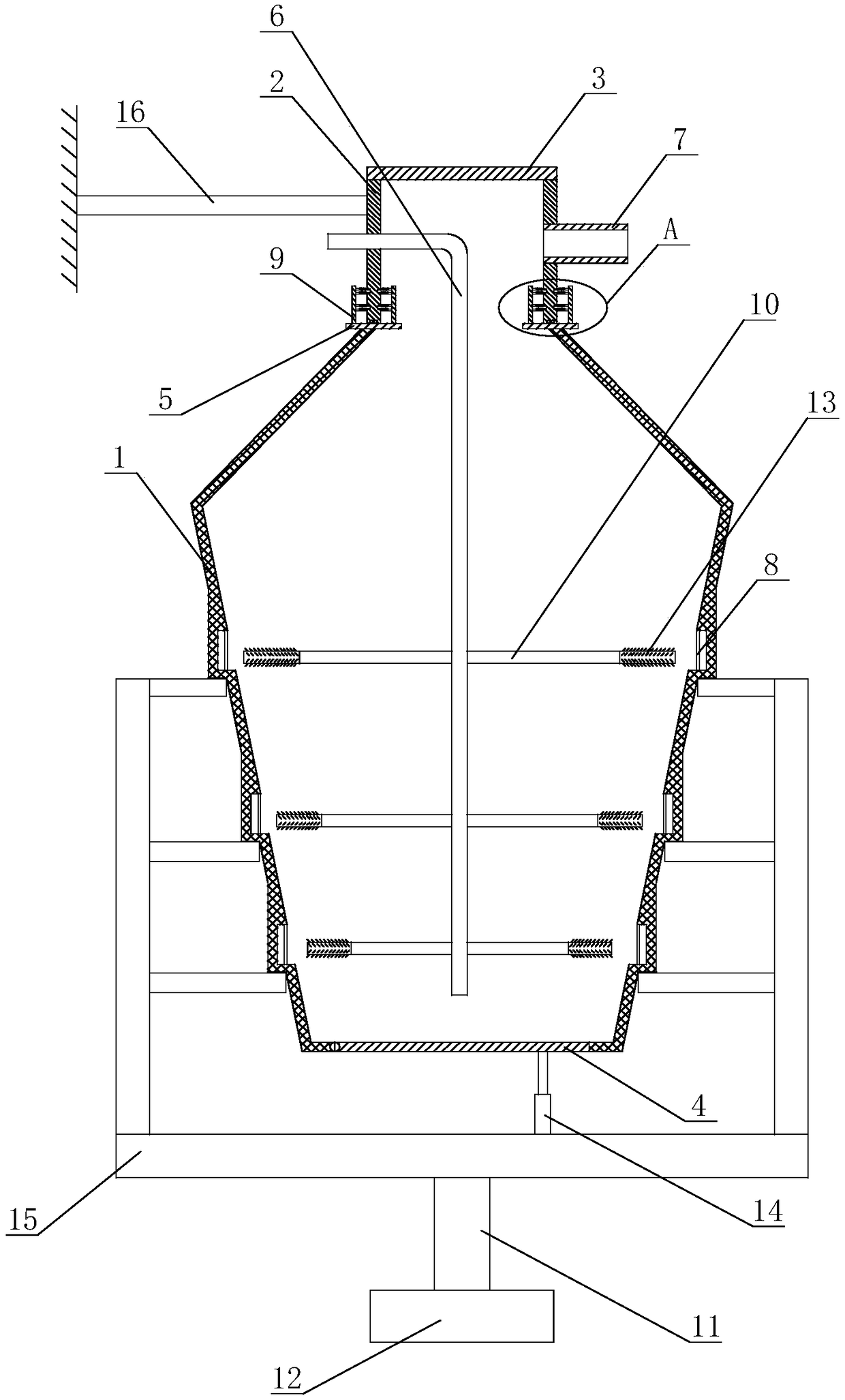
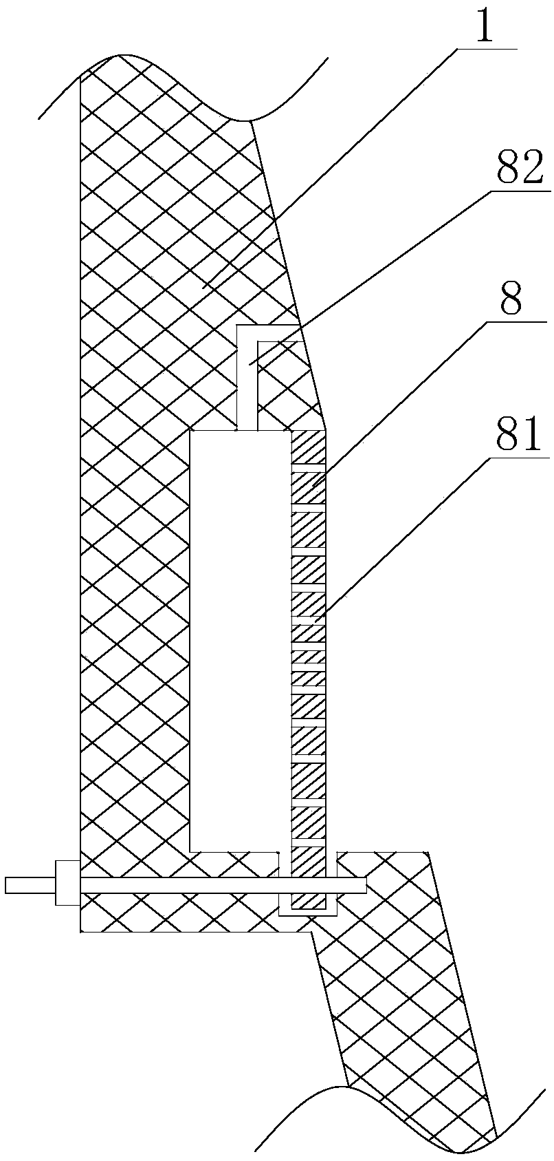
[0046] Such as Figure 1 to Figure 4 The centrifugal screening equipment for isatis shown includes a support frame 15 and a housing 1 arranged in the support frame 15. The support frame 15 is provided with a plurality of horizontal support rods for supporting and fixing the housing 1 , A gap is provided between the bottom surface of the support frame 15 and the lower surface of the housing 1, and the lower surface of the support frame 15 is fixed with a drive rod 11 connected to the output end of the motor 12; the diameter of the housing 1 is from above It gradually increases and then gradually decreases. The top end of the housing 1 is an open end, and the bottom end of the housing 1 is a closed end. The closed end of the housing 1 is provided with a discharge port, and the inside of the discharge port is hinged with The bottom cover 4 is provided with a hydraulic cylinder 14 below the bottom cover 4, and the hydraulic cylinder 14 is fixed on the bottom surface of the support ...
Embodiment 2
[0058] On the basis of embodiment 1, the outer diameter of the slag collecting tank is larger than the outer diameter of the housing 1, and the outer wall of the slag collecting groove forms a protrusion on the outer wall of the housing 1, and the bottom surface of the protrusion is flat and convex. The rising part is detachably fixed on the horizontal support rod of the support frame 15; the air outlet of the extended rubber tube 13 is facing the slag collecting cavity; along the direction from the center of the housing 1 to the inner wall of the housing 1, the inner diameter of the blowing branch pipe 10 Gradually decrease, the inner diameter of the extended rubber tube 13 is equal to the minimum value of the inner diameter of the blast branch pipe 10; the second spring 132 above the spoiler 133 and the second spring 132 below the spoiler 133 are respectively located on the spoiler Two ends of 133; the thickness of the spoiler 133 is 0.5-2.5cm.
Embodiment 3
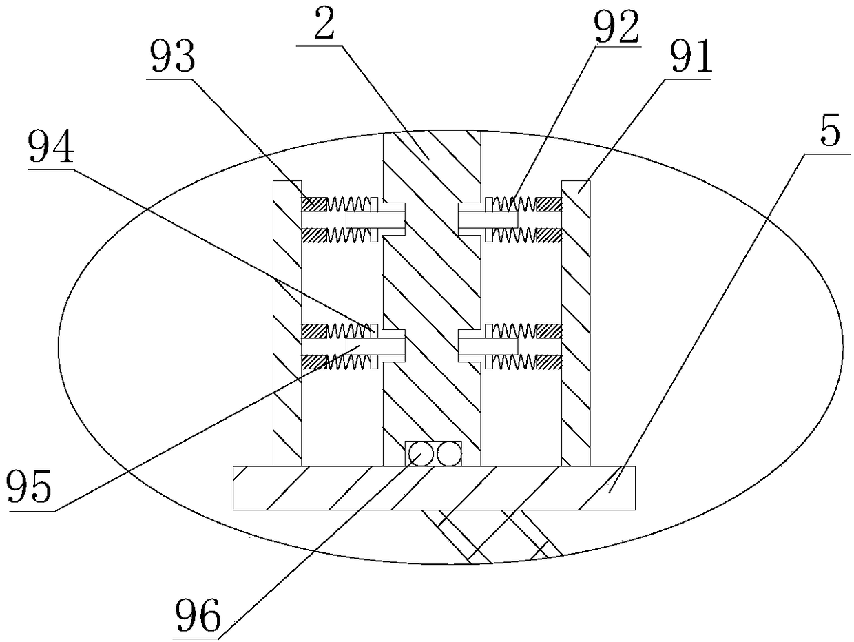
[0060] On the basis of Embodiment 2, a plurality of adaptive stabilization mechanisms 9 are also fixed on the placing table 5. The adaptive stabilization mechanism 9 includes two arc-shaped fixing plates 91 fixed on the placing table 5. A limit zone for limiting the feeding barrel 2 is formed between the two fixed plates 91. A roller 95 is arranged in the limit zone. A pin shaft 94 is arranged in the center of the roller 95. The roller 95 can surround the pin shaft. 94 is rotated, the upper and lower parts of the pin shaft 94 are connected with a first spring 92, the first spring 92 is connected with a support column 93, the support column 93 is fixed on the fixed plate 91; A roller groove is provided on the side wall, and the side surface of the roller 95 squeezes the inner wall of the roller groove; the bottom end of the feeding barrel 2 is provided with a ball groove, and a number of balls 96 are provided in the ball groove.
PUM
 Abstract
Description
Claims
Application Information
 - R&D
- Intellectual Property
- Life Sciences
- Materials
- Tech Scout
- Unparalleled Data Quality
- Higher Quality Content
- 60% Fewer Hallucinations
Browse by: Latest US Patents, China's latest patents, Technical Efficacy Thesaurus, Application Domain, Technology Topic, Popular Technical Reports.
© 2025 PatSnap. All rights reserved.Legal|Privacy policy|Modern Slavery Act Transparency Statement|Sitemap|About US| Contact US: help@patsnap.com


