
Automatic lamination mechanism of Z-type laminated battery core

A kind of laminated and automatic technology, applied in the direction of circuits, electrical components, secondary batteries, etc., can solve the problems of poor controllability of gravity and airflow, complex structure, poor reliability, etc., achieve continuous and reliable operation, and realize automation Production, the effect of continuous automated production

Active Publication Date: 2019-02-26
HEFEI GUOXUAN HIGH TECH POWER ENERGY
View PDF4 Cites 11 Cited by
  • Summary
  • Abstract
  • Description
  • Claims
  • Application Information

AI Technical Summary

Problems solved by technology

The existing processing mechanism cannot realize automatic processing, and after the diaphragm is cut, it relies on the gravity of the diaphragm to complete the tiling of the cut diaphragm through the blowing and suction of the airflow. However, due to the poor controllability of gravity and airflow, this method The reliability of the vacuum adsorption platform is not very good, and the vacuum adsorption platform is required to have a moving function to adjust the position of the diaphragm in real time to ensure the alignment requirements, and its structure is relatively complicated

Method used


Image

  • Automatic lamination mechanism of Z-type laminated battery core
  • Automatic lamination mechanism of Z-type laminated battery core
  • Automatic lamination mechanism of Z-type laminated battery core

Examples


Embodiment Construction

[0051] The present invention will be described in detail below with reference to the accompanying drawings and examples. The examples are preferred implementations of the present invention, and the present invention is not limited to the following implementations and forms.

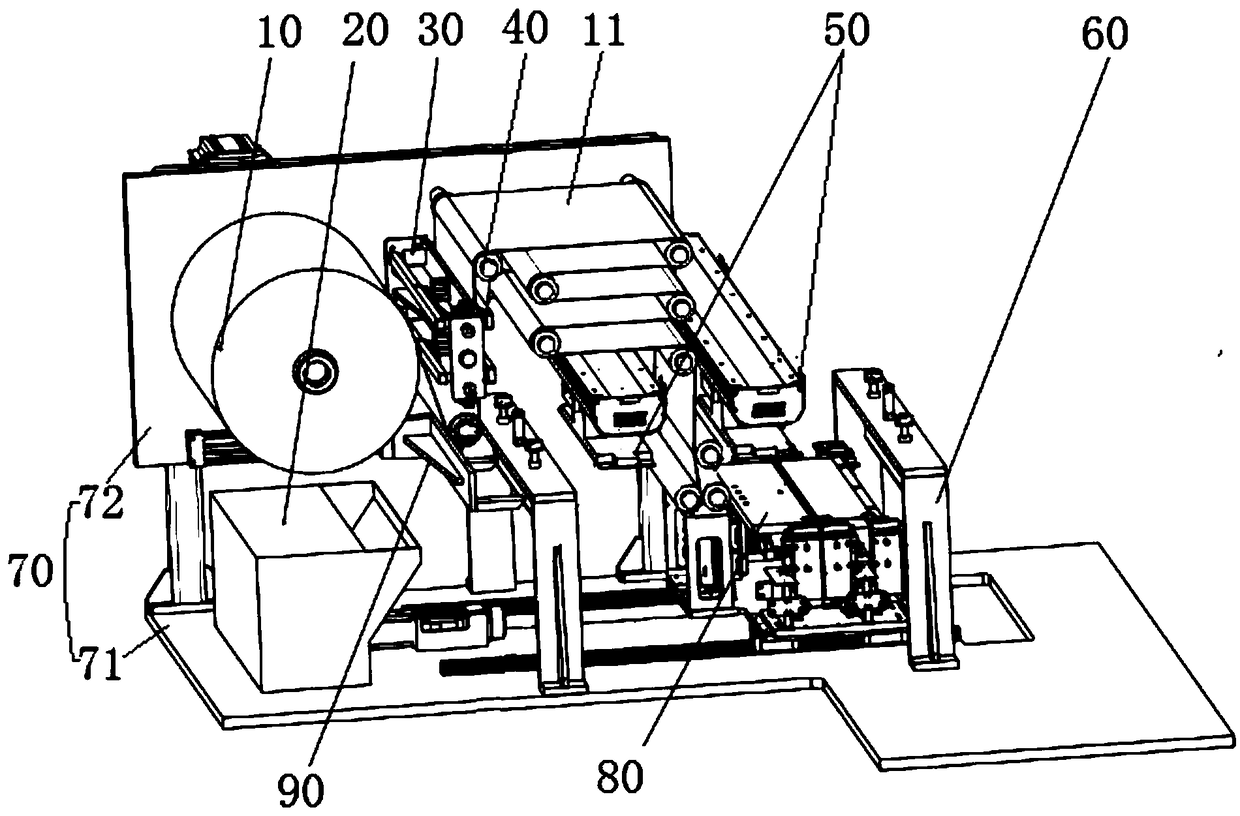
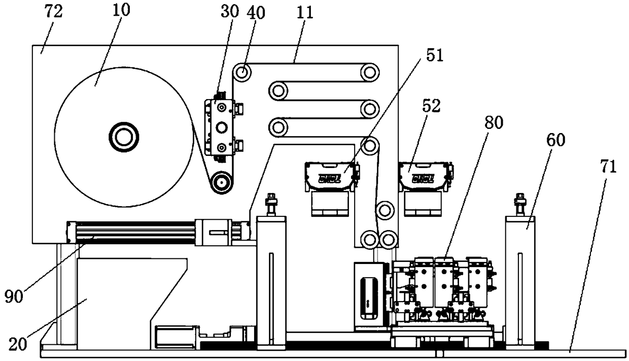
[0052] like figure 1 , 2 As shown, an automatic stacking mechanism for a Z-type laminated battery cell includes a bracket 70 composed of a bottom plate 71 and a side plate 72. The side plate 72 is fixed with a diaphragm unwinding mechanism 10 and is used to align the diaphragm 11 The traction group 40 controlled by tension and deviation correction, the base plate 71 is slidably connected with a lamination table 80, and two cutting mechanisms 60 are symmetrically fixed on the base plate 71 located on both sides of the lamination table 80, which is convenient for lamination The diaphragms at both ends of the platform 80 are moved to be cut off respectively; two pole piece manipulators 50 for placing positi...


PUM


Abstract

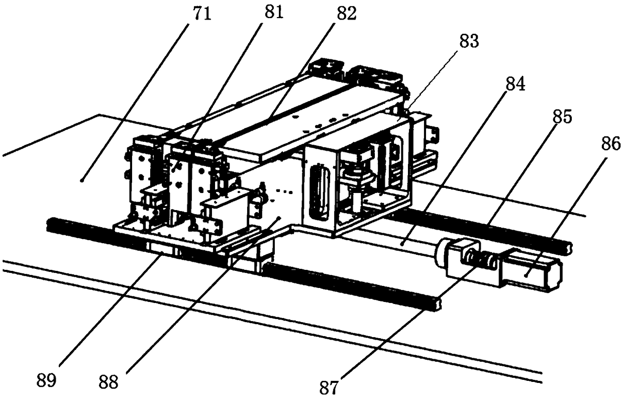
The invention discloses an automatic lamination mechanism of a Z-type laminated battery core, the automatic lamination mechanism comprises a bracket composed of a bottom plate and a side plate, wherein the side plate is fixedly provided with a diaphragm unwinding mechanism, and a traction group used for controlling the tension and the deviation of a diaphragm, the bottom plate is slidably connected with a lamination table, and a cutting mechanism is fixed on the bottom plate; the side plate above the lamination table is fixedly provided with two pole piece manipulators for respectively placingpositive and negative pole pieces; the lamination table includes a work table and pressing holding members which are symmetrically disposed at both ends of the work table and used for pressing and holding of the work table, a lifting mechanism is connected to one side of the work table by a supporting frame, the pressing member, and the pressing holding members and the lifting mechanism are fixedon a moving plate to achieve horizontal movement. The automatic lamination mechanism realizes the automatic continuous operation of automatic cutting, tiling, splicing, automatic discharging and thelike of the diaphragm by a mechanical means, and realizes the cutting and tiling of the diaphragm by the pressing holding members, ensures that the diaphragm is automatically flattened after each electric core is made to achieve continuous automated production.

Description

technical field [0001] The invention relates to a preparation machine for lithium-ion batteries, in particular to an automatic lamination mechanism for Z-type lamination electric cores. Background technique [0002] Lithium-ion power batteries are mainly used for the energy supply of new energy vehicles and are the core components of electric vehicles. In the manufacturing process of lithium-ion batteries, there are both winding structures and laminated structures. Compared with laminated batteries, the wound battery has the advantages of high production efficiency and simple and easy control of the process; however, due to the uneven internal structure of the wound battery, it is inevitable that the tension at each position will be inconsistent during the cycle. deformation, resulting in poor consistency and even a great potential safety hazard. Compared with the wound battery, the battery performance of the laminated battery has been greatly improved, but the positive an...

Claims


Application Information

Patent Timeline
IPC IPC(8): H01M10/0585
CPCH01M10/0585Y02E60/10Y02P70/50
Inventor 朱大超吴尽高二平王晨旭
Owner HEFEI GUOXUAN HIGH TECH POWER ENERGY
Learn More