
Inductive Coil Structure and Inductively Coupled Plasma Generation System

A technology of inductance coil and plasma, applied in the field of ICP generation system, which can solve the problems of low discharge stability and low plasma density

Active Publication Date: 2021-09-14
EN2CORE TECH INC
View PDF12 Cites 0 Cited by
  • Summary
  • Abstract
  • Description
  • Claims
  • Application Information

AI Technical Summary

Problems solved by technology

However, the traditional inductor coil structure has low discharge stability and low plasma density

Method used


Image

  • Inductive Coil Structure and Inductively Coupled Plasma Generation System
  • Inductive Coil Structure and Inductively Coupled Plasma Generation System
  • Inductive Coil Structure and Inductively Coupled Plasma Generation System

Examples


Embodiment Construction

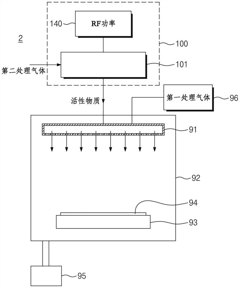
[0049] A high voltage potential (3 kv or more) is applied in the dielectric discharge tube at low pressure (less than a few tens of Torr without fluid effects) in an antenna arranged around the dielectric discharge tube. In this case, plasma is generated in the dielectric discharge tube. The surface of the dielectric discharge tube is heated by ion collisions. Therefore, the dielectric discharge tube is heated to a temperature above 1000°C. This can lead to changes in the surface properties of the dielectric discharge tube or perforation of the dielectric discharge tube.

[0050] The high potential applied to the antenna is affected by the antenna's inductance, frequency and current. Under high power conditions, a high potential must be applied to the antenna. Therefore, it is necessary to reduce the high potential of the antenna.

[0051] According to some embodiments of the inventive concept, in the case of applying a high power of several kW or more, a method of reducin...


PUM


Abstract

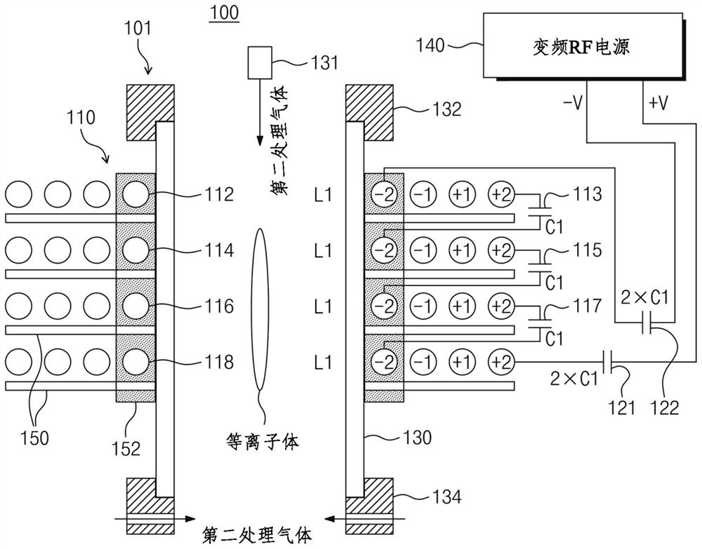
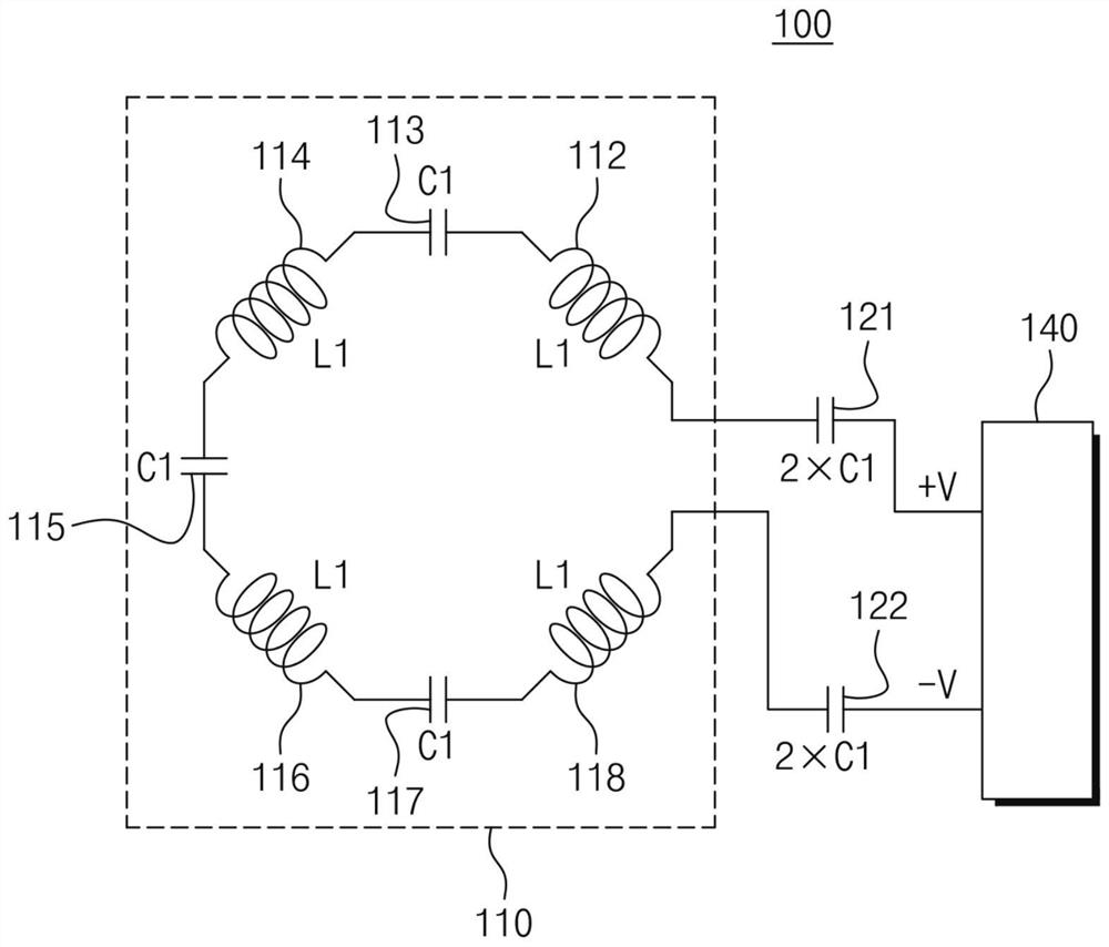
The inductively coupled plasma (ICP) generation system of the present invention comprises: a dielectric tube extending lengthwise; a first inductive coil structure arranged to surround the dielectric tube and generate ICP in the dielectric tube An RF power supply configured to provide positive power and negative power with opposite phases to supply positive power and negative power of the RF power to both ends of the first inductive coil structure, respectively, and the RF power supply is configured to change the driving frequency; a main capacitor, the first main capacitor disposed between the positive output terminal of the RF power supply and one end of the first inductive coil structure; and a second main capacitor disposed between the between the negative output terminal of the RF power supply and the other end of the first inductance coil structure. The first inductive coil structure includes: an inductive coil connected in series with each other and placed in different layers, and the inductive coil has at least one turn in each layer; and an auxiliary capacitor, the auxiliary capacitor are respectively arranged between adjacent ones of the induction coils to distribute the voltage applied to the induction coils.

Description

technical field [0001] The present invention relates to an inductively-coupled plasma (ICP: inductively-coupled plasma) generating system, and in particular, to an ICP generating system including a capacitor inserted between a plurality of antennas and having a voltage dividing structure. Background technique [0002] Plasmas are used in processes to etch substrates (eg, semiconductor wafers) or to deposit layers on substrates. Furthermore, plasmas are used for the synthesis of new materials, surface treatment and environmental purification. In addition, atmospheric pressure plasma is used in plasma scrubbers, cleaning, sterilization and skin care. [0003] To generate a conventional inductively coupled plasma (ICP), a dielectric discharge tube wound by an induction coil is used. However, the conventional inductive coil structure has low discharge stability and low plasma density. [0004] The present invention provides a novel inductive coil structure configured to stabl...

Claims


Application Information

Patent Timeline
Patent Type & Authority Patents(China)
IPC IPC(8): H01J37/32H01Q1/26H01Q1/52H05H1/46
CPCH01J37/3211H01Q1/26H01Q1/521H01J37/32174H01J37/321H05H1/4652
Inventor 严世勋李润星
Owner EN2CORE TECH INC
Learn More