Medical deflectable grinding head

A grinding head and outer tube technology, applied in the field of medical deflectable grinding head, can solve problems such as unreliable stability, hidden safety hazards, and affecting surgical safety, and achieve the effect of improving surgical safety

Pending Publication Date: 2019-03-08
NINGBO HICREN BIOTECH
View PDF1 Cites 4 Cited by
  • Summary
  • Abstract
  • Description
  • Claims
  • Application Information

AI Technical Summary

Problems solved by technology

In orthopedic surgery, grinding, as a precision machining method, has been widely used to remove bone tissue material. Usually, the grinding head is inserted into the human body and the power handle is used to directly drive the grinding head for grinding. In general, it is difficult to control the grinding position of the grinding head through external force, which leads to low operation efficiency and certain safety hazards
[0003] At present, in order to solve the control of the grinding angle of the grinding head, a mechanical pitching type grinding head has appeared in the prior art. For example, Chinese patent CN103767759B discloses a medical grinding tool, which includes a knife tube assembly and is installed on the front end of the knife tube assembly. The grinding head is set in such a way that it can be driven to pitch and rotate. The tail end of the grinding head is hinged to the inner knife tube. The patented front end grinding head adopts a articulated mechanical structure. The grinding head is pitched, so as to realize the control of the grinding position of the grinding head, but because the grinding head end of the medical grinding tool is mechanically articulated, its structure is complex, there are many parts, and many parts need to bear a certain load, which is So that the

Method used


Image

  • Medical deflectable grinding head
  • Medical deflectable grinding head
  • Medical deflectable grinding head

Examples


Embodiment 1

[0051] This embodiment is a preferred medical deflectable grinding head.

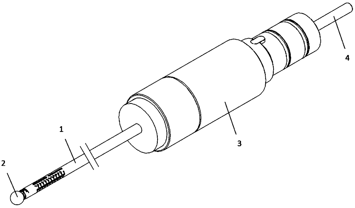
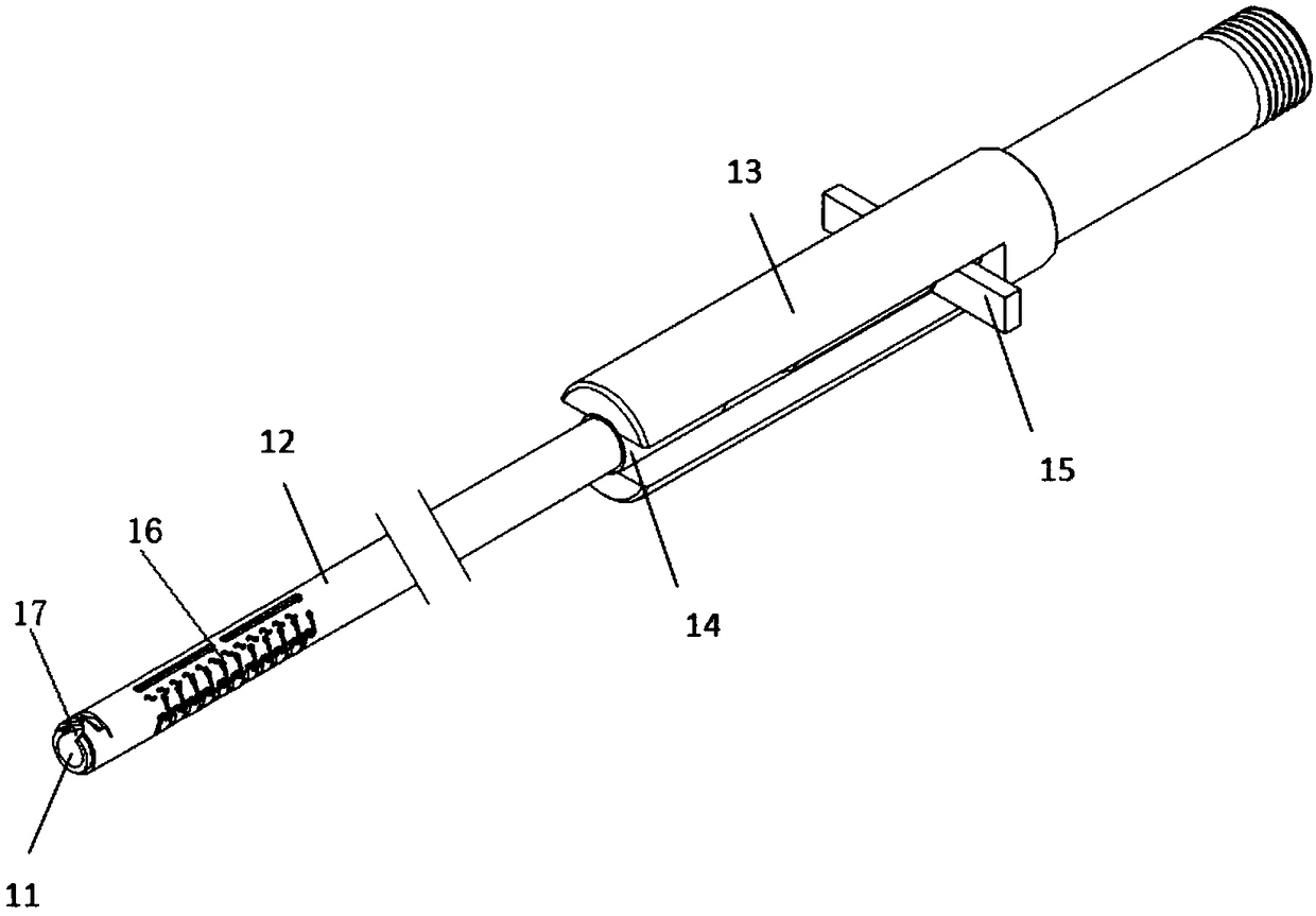
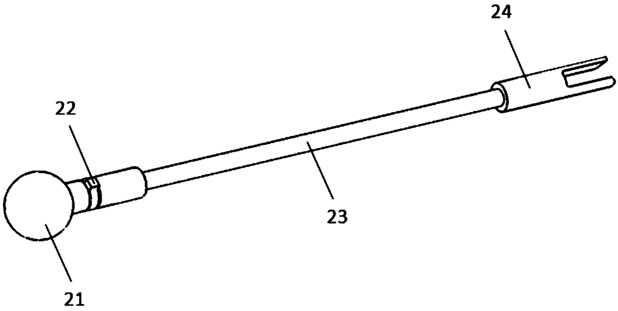
[0052] like Figure 1 to Figure 8 As shown, the medical two-way deflectable grinding tool of this embodiment includes a deflectable tube assembly 1, a grinding head assembly 2 installed at the far end of the deflectable tube assembly 1, a proximal handle 3 and a deflectable tube assembly. 1 internal transmission assembly 4. The deflectable tube assembly 1 can be driven by the handle 3 to deflect in two directions, thereby driving the front end grinding head 21 to deflect. The deflectable tube assembly 1 is composed of inner and outer tubes, and the distal end is fixedly connected (welded). Both the inner tube 11 and the outer tube 21 of the deflectable tube assembly 1 have a proximal notch 16 and a distal notch 17 in the axial direction, and the notches of the inner tube 21 and the outer tube 22 are relatively distributed.

[0053] The deflectable tube assembly 1 comprises an inner tube 11 , an outer...

Embodiment 2

[0059] This embodiment is an alternative embodiment of the first embodiment, which only optimizes the structure of the barb-shaped incision and the straight-shaped incision on the inner tube and the outer tube.

[0060] In this example, if Figure 9-10 As shown, the width of the barb-shaped incision on the inner tube is wide in the middle and narrow at both ends, and two straight bar-shaped incisions are provided; the barb-shaped incision on the outer tube 12 is wide in the middle and narrow at both ends, and two bar-shaped incisions are provided Straight cuts, wherein the straight cuts on the inner tube 11 and the exterior 12 are arranged on opposite sides.

[0061] In this embodiment, the cutting barbs of the inner tube and the outer tube are less cut on both sides, more cut in the middle, more uncut parts on both sides are reserved, and the middle is the maximum bending point of the deflectable tube assembly, so as not to increase bending resistance. Improve the connection...

Embodiment 3

[0063] This embodiment is an alternative embodiment of the first embodiment, which only optimizes the structure of the barb-shaped incision and the straight-shaped incision on the inner tube and the outer tube.

[0064] In this example, if Figure 11-12 As shown, the width of the barb-shaped incision on the inner tube is wide at the far end and narrow at the proximal end, and a straight bar-shaped incision with a larger width (compared with Embodiments 1 and 2) is set; the inverted hook on the outer tube 12 The hook-shaped incision is wide at the far end and narrow at the proximal end, and two straight strip-shaped incisions with larger widths (compared with Embodiments 1 and 2) are provided, wherein the straight strip-shaped incisions on the inner tube 11 and the appearance 12 are set on the same side.

[0065] In this embodiment, the wide straight seam of the inner tube and the outer tube cooperates with the cutting width of the proximal end to gradually decrease, which red...


PUM


Abstract

The invention relates to a medical deflectable grinding head. The medical deflectable grinding head comprises a deflectable tube assembly, a grinding head assembly, a handle and a transmission assembly; the deflectable tube assembly adopts a stainless steel tube cutting deflection scheme, front-back displacement of an outer tube is converted from screw rotation of the handle, the outer tube and aninner tube are mutually pulled when the outer tube is locked, and rigid support of the grinding head is achieved; by means of proximal incisions formed in the inner tube and the outer tube, two-way deflection of the deflectable tube assembly can be achieved; the transmission assembly is connected with the grinding head so as to achieve rotation of the grinding head through external drive. According to the medical deflectable grinding head, rigid support to the head end is achieved, and a work end of the grinding head has the smaller external diameter, and can pass through a smaller minimallyinvasive channel; by means of an inverted-hook-shaped incision, the phenomena that the incision overbends, and the grinding head is broken are prevented, and the surgical operation accuracy and the surgical safety are improved conveniently; meanwhile, the structure of the handle is improved, and assembling and using of operators are facilitated.

Description

technical field [0001] The invention relates to the technical field of orthopedic surgery medical instruments, in particular to a medical deflectable grinding head. Background technique [0002] In recent years, various bone tissue diseases such as hyperosteogeny, fracture, and osteoarthritis are increasing, and the requirements for bone surgery are also getting higher and higher. In orthopedic surgery, grinding, as a precision machining method, has been widely used to remove bone tissue material. Usually, the grinding head is inserted into the human body and the power handle is used to directly drive the grinding head for grinding. Among them, it is generally difficult to control the grinding position of the grinding head through external force, which leads to low operation efficiency and certain safety hazards. [0003] At present, in order to solve the control of the grinding angle of the grinding head, a mechanical pitching type grinding head has appeared in the prior a...

Claims


Application Information

Patent Timeline
IPC IPC(8): A61B17/16
CPCA61B17/16A61B2017/1602
Inventor 姚益奇卓清山张鹏云俞凯杰
Owner NINGBO HICREN BIOTECH
Why Eureka
Try Eureka