Stator module for electric spindle, and permanent magnet synchronous electric spindle

A permanent magnet synchronous and electric spindle technology, applied in positioning devices, large fixed members, maintenance and safety accessories, etc., can solve the problem that the cooling rate cannot be further improved, the spiral cooling circuit cannot increase the coolant flow rate, and the cooling capacity is insufficient and other problems, to achieve the effect of small temperature gradient, increased flow rate and improved cooling capacity

Pending Publication Date: 2019-03-08
深圳市爱贝科精密工业股份有限公司
View PDF0 Cites 7 Cited by
  • Summary
  • Abstract
  • Description
  • Claims
  • Application Information

AI Technical Summary

Problems solved by technology

[0002] In the electric spindle device of the prior art, the electric spindle needs to have a built-in motor stator assembly, which is usually directly assembled on the steel cylinder of the spindle, and the motor stator assembly is cooled through the cooling channel inside the steel cylinder or the water cooling jacket with a spiral cooling circuit outside the stator assembly, cooling Insuffici

Method used


Image

  • Stator module for electric spindle, and permanent magnet synchronous electric spindle
  • Stator module for electric spindle, and permanent magnet synchronous electric spindle
  • Stator module for electric spindle, and permanent magnet synchronous electric spindle

Examples


Example Embodiment

[0043] Example one

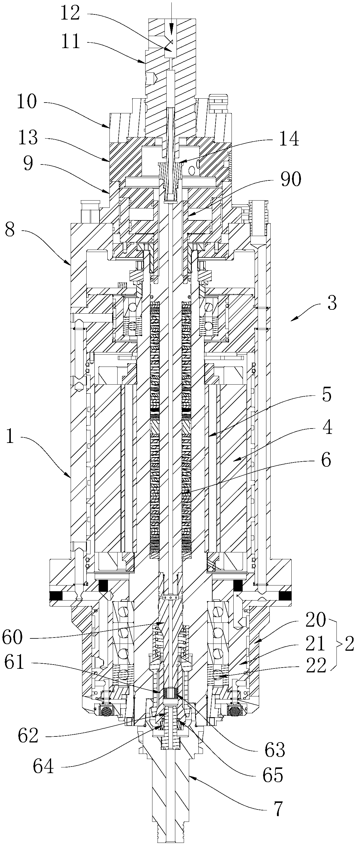
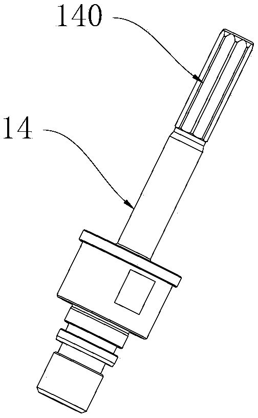
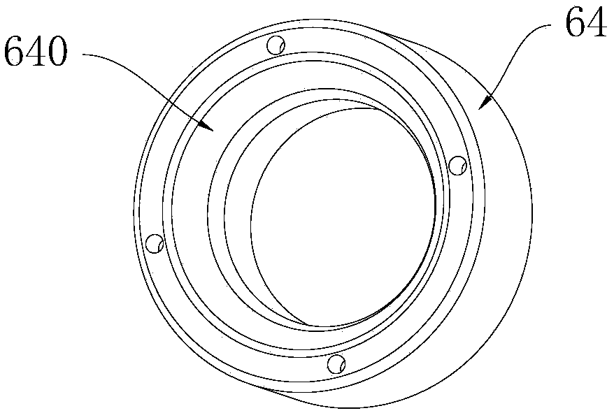
[0044] This embodiment proposes a stator assembly of an electric spindle, please refer to figure 1 , Figure 13 with Figure 14 , Which includes a stator core 40, the outer side of the stator core 40 is provided with a cooling jacket 42, the outer side wall of the cooling jacket 42 is provided with a plurality of annular annular grooves 43, between two adjacent annular grooves 43 The straight slots 44 are connected, and two adjacent straight slots 44 are alternately arranged on the left and right sides of the stator core 40. By the cooperation of the straight slots 44 and the annular slots 43, the straight slots 44 The introduced cooling liquid flows to both sides of the annular groove 43.

[0045] In the above-mentioned stator assembly 4, the cooling liquid flows from the steel cylinder of the electric spindle into the annular groove 43 at one end of the stator core 40, and is divided into a forward and reverse flow through the straight groove 44 and passes th...

Example Embodiment

[0052] Example two

[0053] This embodiment proposes a built-in permanent magnet synchronous electric spindle, which combines Figure 1 to Figure 12 As shown, it includes a steel cylinder 1, a front bearing assembly 2 is provided at the front end of the steel cylinder 1, a rear bearing assembly 3 is provided at the rear end of the steel cylinder 1, and a stator assembly 4 is fixed in the steel cylinder 1 , The stator assembly 4 is provided with a hollow rotor assembly 5, the front and rear ends of the rotor assembly 5 respectively pass through the front bearing assembly 2 and the rear bearing assembly 3, and the rotor assembly 5 is penetrated with a hollow The front end of the rotor assembly 5 is used to install a hollow knife handle 7, the front end of the rod 6 is connected to the knife handle 7 and the internal passages of the two are connected to each other, and the rear end of the steel cylinder 1 A back cover 8 is fixed. The back end of the rotor assembly 5 extends into the...

Example Embodiment

[0066] Example three

[0067] During the use of the electric spindle, the interface end face of the rotor assembly of the electric spindle is a single plane. When working, the tool holder interface surface may be contaminated due to the poor dust-proof and iron slag-proof performance of the machine tool during operation, resulting in a decrease in the accuracy of the spindle tool clamping In addition, most of the built-in motors of the existing electric spindles are asynchronous motors. Due to the defects of the aluminum casting process, the aluminum casting rotor built in the asynchronous motor is prone to uneven densities of aluminum bars, which makes the motor easy to jitter and the physical parameters are stable. Poor performance results in weak spindle orientation rigidity and poor operating speed accuracy. When the spindle is re-cutting with a large disk tool at low speed, the speed will jitter, which cannot further improve the processing efficiency and the surface finish, a...


PUM


Abstract

The invention discloses a stator module for an electric spindle. The stator module for the electric spindle comprises a stator iron core, wherein a cooling sleeve is arranged on the outer side of thestator iron core; multiple annular ring-shaped slots are formed in the outer side wall of the cooling sleeve; each two adjacent ring-shaped slots communicate through a straight slot; each two adjacentstraight slots are formed in the left side and the right side of the stator iron core in a staggering way; and through the cooperation of the straight slots and the ring-shaped slots, cooling liquidintroduced through the straight slots flow to two sides of the ring-shaped slots. The stator module for the electric spindle provided by the invention has the characteristics that the flow of the cooling liquid can be increased, the temperature is uniform after cooling, the temperature gradient at a cooling liquid inlet part and a cooling liquid outlet part is small, and the cooling capacity is high.

Description

Technical field [0001] The invention relates to an electric spindle, in particular to a stator assembly of the electric spindle and a permanent magnet synchronous electric spindle. Background technique [0002] In the prior art electric spindle device, the electric spindle needs to have a built-in motor stator assembly, which is usually directly assembled on the spindle steel cylinder, and the motor stator assembly is cooled through a cooling channel inside the steel cylinder or a water cooling jacket with a spiral cooling circuit outside the stator assembly. Insufficient capacity. The former S-shaped vertical cooling circuit makes the main shaft steel cylinder present a temperature gradient along the circumferential direction, while the latter presents a larger temperature gradient at the front and rear ends of the stator (that is, the axial direction). The cooling circuit cannot increase the coolant flow rate, and the cooling rate cannot be further increased. Summary of the in...

Claims


Application Information

Patent Timeline
IPC IPC(8): B23B19/02B23Q3/155B23Q11/10B23Q11/12
CPCB23Q1/70B23Q3/155B23Q11/10B23Q11/127
Inventor 农乃昌
Owner 深圳市爱贝科精密工业股份有限公司
Why Eureka
Try Eureka