Energy-saving type wall painting device
An energy-saving, wall technology, applied in construction, building structure, etc., can solve the problems of inability to achieve uniformity, leakage of paint slurry, high labor intensity, etc., to improve the quality of wall construction, construction quality improvement, operation handy effect
- Summary
- Abstract
- Description
- Claims
- Application Information
AI Technical Summary
Problems solved by technology
Method used
Image

Examples
Embodiment 1
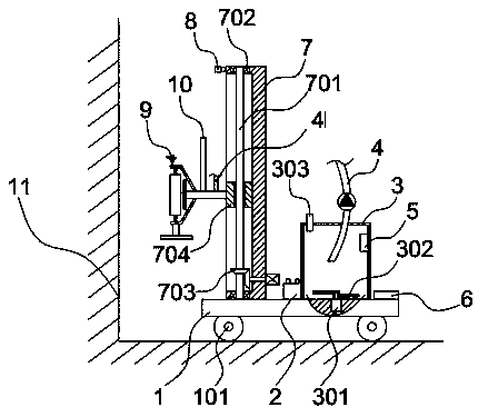
[0026] Such as Figure 1-4 As shown, the energy-saving wall painting device includes a bottom plate 1 on which a material barrel 3 and a lifting plate 7 are arranged respectively on the top, and a liftable painting mechanism 9 is provided on the side of the lifting plate 7, and the painting mechanism 9 passes through the discharge pipe 4 and the material barrel. 3 connection, the discharge pipe 4 is connected with a pump body, the bottom plate 1 is provided with a motor 301 whose output shaft is in the material barrel 3, the output shaft is staggered with stirring blades 302 with different heights, and the upper part of the inner wall of the material barrel 3 is at least connected with A monitor 5 and a computer 6 are arranged on the bottom plate 1 . The wall 11 is painted by mechanical equipment instead of manual painting, which reduces the labor force and improves the quality of mechanical operation. The whole painting process is monitored by the computer 6, and the paramete...
Embodiment 2
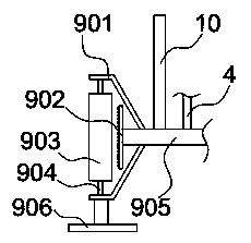
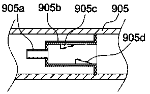
[0036] When the energy-saving wall painting device of the present invention is actually working: pour the cement slurry raw materials for painting into the barrel 3, stir the raw materials through the motor 301 to prevent the raw materials from sinking or delamination, and push the device to the wall through the roller 101 Near 11, control the brushing distance, start the pump body on the discharge pipe 4 to extract the cement mortar and transport it to the connecting pipe 905, and the spray pipe 902 will spray the mortar out to drive the roller brush wheel 903 to rotate, and spray the brush slurry to the roller brush at the same time Feed is realized on the wheel 903, and the lifting mechanism 7 drives the screw rod 701 to rotate through the bevel gear set 703 to drive the lifting block 704 to lift up and down, and drives the roller brush wheel 903 to lift up and down to paint the wall 11. After the wall 11 is painted, it is improved. The construction speed of the wall body ca...
PUM
 Abstract
Description
Claims
Application Information