Dual-fuel engine adopting main and auxiliary oil injectors and manifolds for multiple times of spraying, and combustion organization method of dual-fuel engine

A dual-fuel engine and multiple injection technology, which is applied to combustion engines, machines/engines, internal combustion piston engines, etc., can solve problems such as which combustion mode is not considered, so as to improve misfire and knocking problems and accelerate flame propagation Speed, burn time shortening effect

Active Publication Date: 2019-03-08
HARBIN ENG UNIV
View PDF5 Cites 12 Cited by
  • Summary
  • Abstract
  • Description
  • Claims
  • Application Information

AI Technical Summary

Problems solved by technology

However, these patents did not consider which combustion mode to use under which working conditions, how to organize the mixture gas formation and high-efficiency and low-emission combustion in the main combustion chamber, and did not propose how to improve the stable ignition of the engine under the gas mode.

Method used


Image

  • Dual-fuel engine adopting main and auxiliary oil injectors and manifolds for multiple times of spraying, and combustion organization method of dual-fuel engine
  • Dual-fuel engine adopting main and auxiliary oil injectors and manifolds for multiple times of spraying, and combustion organization method of dual-fuel engine
  • Dual-fuel engine adopting main and auxiliary oil injectors and manifolds for multiple times of spraying, and combustion organization method of dual-fuel engine

Examples


Embodiment Construction

[0032] The present invention will be further described below in conjunction with accompanying drawing:

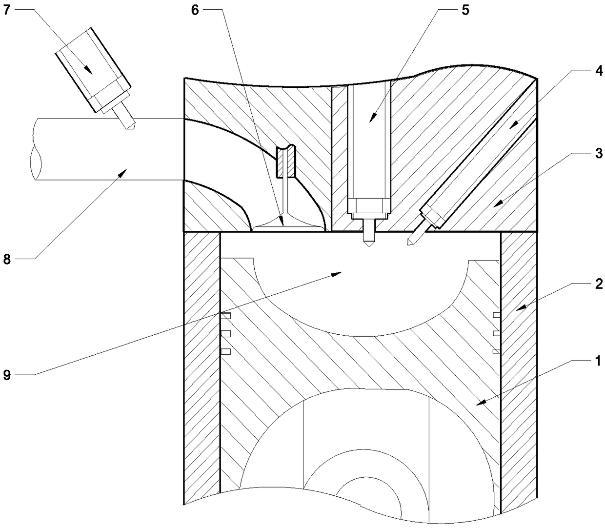
[0033] as attached figure 1 As shown, it is a specific layout diagram of the dual-fuel engine combustion system in the embodiment of the present invention. The structure of the dual-fuel engine combustion system using main and auxiliary injectors and manifold multiple injections includes: piston 1, cylinder liner 2, cylinder head 3 , auxiliary injector 4, main injector 5, intake valve 6, manifold low-pressure gas injection device 7, intake passage 8, combustion chamber 9. The combustion chamber is composed of the upper surface of the piston, the peripheral wall of the cylinder liner and the lower surface of the cylinder head; the main and auxiliary injectors are installed in the cylinder head, the main injector is located in the center of the cylinder head, and its axis coincides with the axis of the cylinder, and the auxiliary injector is installed on the On the right sid...


PUM


Abstract

The invention belongs to the technical field of combustion of internal combustion engines, and particularly relates to a dual-fuel engine adopting main and auxiliary oil injectors and manifolds for multiple times of spraying, and a combustion organization method of the dual-fuel engine. The dual-fuel engine comprises a piston, an air cylinder sleeve, an air cylinder cover, the main oil injector, the auxiliary oil injector, a manifold low-pressure gas jetting device and the like; the main oil injector is mounted at the center of the air cylinder cover, and the diesel injection ratio during thelow load can be controlled by changing the oil spraying pulse width of the main oil injector; the auxiliary oil injector is obliquely mounted on the air cylinder cover, diesel micro-jet is conducted during the middle and high load, and natural gas is ignited after diesel nearby a top dead center is self-ignited; and a manifold low-pressure gas jetting valve is mounted on the gas inlet manifold ofeach cylinder, during the middle and high load, the number of times of jetting and the timing of the low-pressure gas jetting valves are controlled, and thus reasonable mixed gas concentration distribution is formed in the cylinders. According to the dual-fuel engine, ignition stability under different working conditions is ensured through diesel ignition, and different oil and gas jetting strategies are adopted under the different working conditions, so that reasonable oil and gas distribution is achieved in the cylinders to achieve the good combustion effect, and thus the economical efficiency and emission performance of the engine are improved.

Description

technical field [0001] The invention belongs to the technical field of combustion of internal combustion engines, and in particular relates to a dual-fuel engine with multiple injections from main and auxiliary injectors and manifolds and a combustion organization method thereof. Background technique [0002] Diesel / natural gas dual-fuel engines can operate in two fuel modes, and are economical, and the cost of modification is generally lower than that of directly using gas fuel engines. At the same time, the biggest advantage of dual fuel is that it can reduce NOx and PM emissions at the same time, which is difficult to achieve in traditional diesel engines. Relevant tests have shown that the NOx emission of dual-fuel engines is lower than that of diesel engines, and can be reduced by about 50% at medium and low loads. At the same time, the particulate matter emissions of dual-fuel engines can be reduced by nearly 70% compared with diesel engines, and the effect is quite si...

Claims


Application Information

Patent Timeline
Patent Type & Authority Applications(China)
IPC IPC(8): F02B69/04F02D19/08F02D19/06F02D41/30
CPCF02B69/04F02D19/0647F02D19/0686F02D19/081F02D41/3094Y02T10/30
Inventor 杨立平何永恒王立媛宋恩哲姚崇孙军
Owner HARBIN ENG UNIV
Why Eureka
Try Eureka