
Flue gas treatment system of boiler

A technology for processing system and boiler flue gas, which is applied in the direction of gas treatment, combustion product treatment, climate sustainability, etc., can solve the problems of huge equipment, limited waste heat recovery effect, equipment corrosion, etc., to reduce the moisture absorption load, Good economic benefits and the effect of increasing the return water temperature

Pending Publication Date: 2019-03-08
TSINGHUA UNIV
View PDF0 Cites 1 Cited by
  • Summary
  • Abstract
  • Description
  • Claims
  • Application Information

AI Technical Summary

Problems solved by technology

[0003] However, in the existing flue gas treatment process, it often occurs that the treated flue gas is low-temperature saturated flue gas, which is easy to condense and produce "white smoke", and the low-temperature flue gas is not easy to spread, and sometimes needs to be reheated; it cannot be directly To recover high-quality water, the condensed water must either be drained or be used after subsequent treatment; the waste heat recovery effect is limited, and a large amount of latent heat in the flue gas cannot be recovered; the waste heat recovery cost is high; the equipment is relatively large, and the nitrogen oxide removal effect is not good Obvious; the circulating medium (solution) is easily polluted; technical problems such as equipment corrosion

Method used


Image

  • Flue gas treatment system of boiler
  • Flue gas treatment system of boiler

Examples


Embodiment Construction

[0062] In order to have a clearer understanding of the technical solutions, objectives and effects of the present invention, the specific implementation manners of the present invention will now be described with reference to the accompanying drawings.

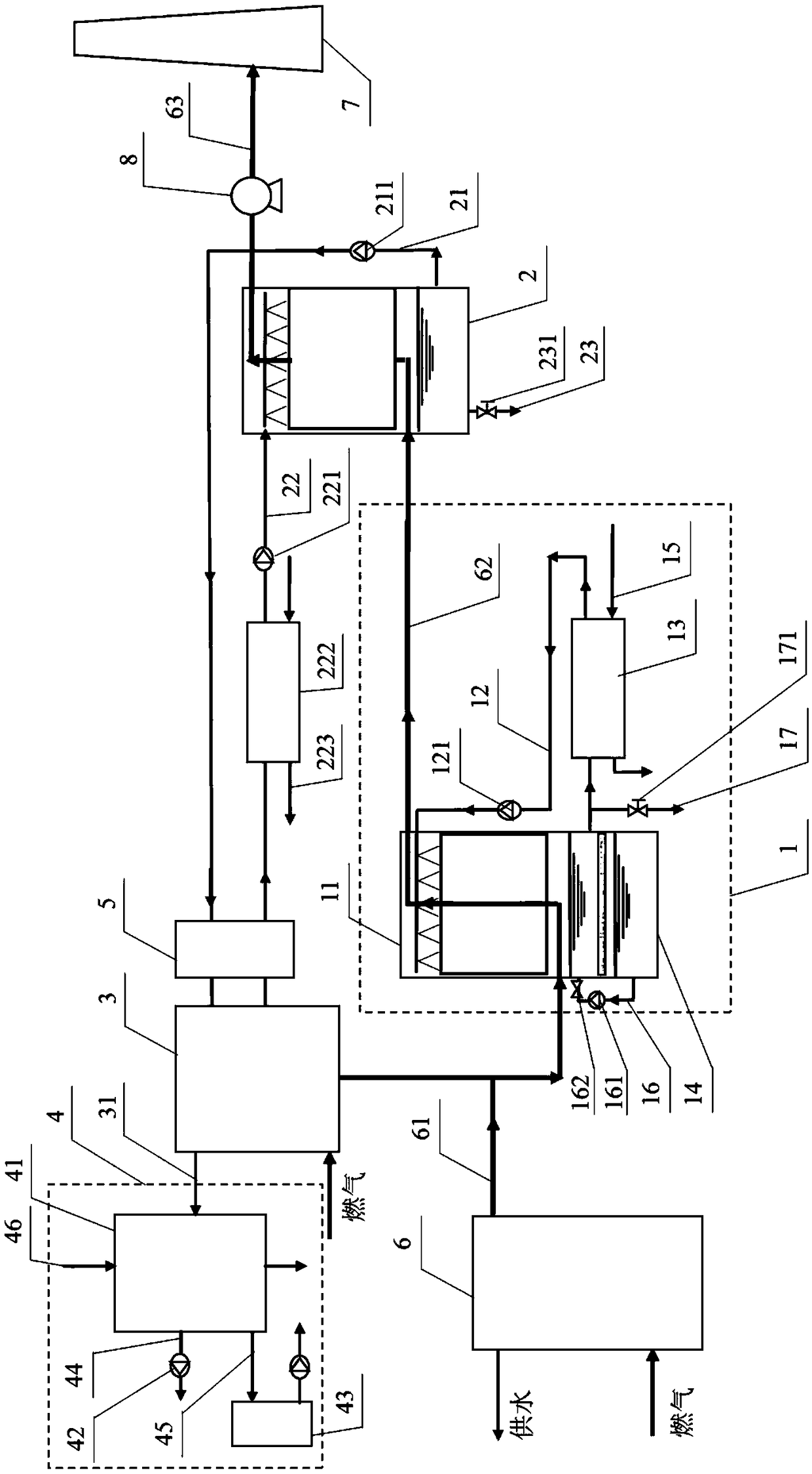
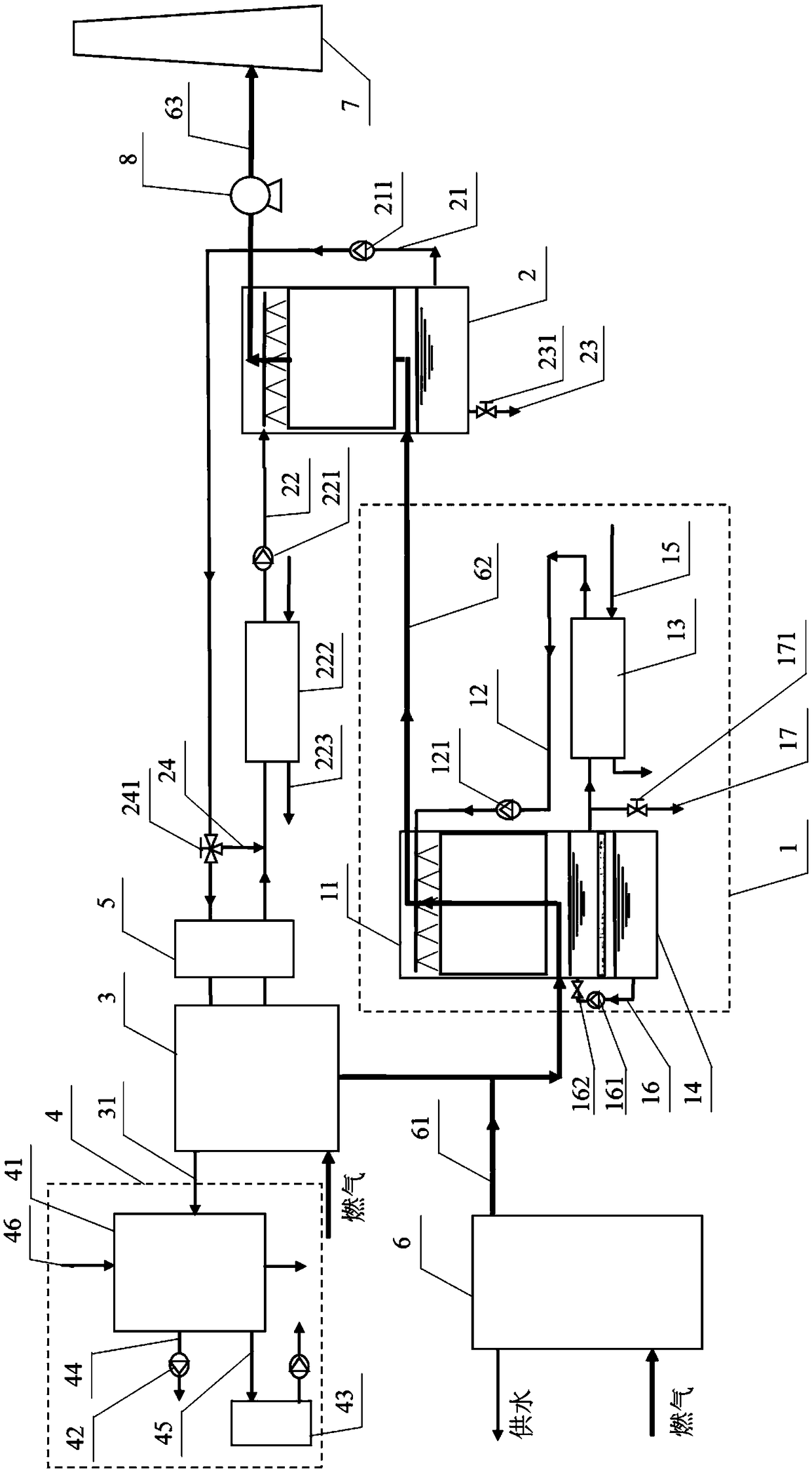
[0063] likefigure 1 and figure 2 As shown, the present invention provides a boiler flue gas treatment system, wherein the boiler flue gas treatment system includes a flue gas condensing unit 1, an absorber 2, a regenerator 3, a steam condensing unit 4 and a plurality of return water branch pipes, the flue gas The condensing unit 1 communicates with the boiler 6 through the first exhaust pipe 61, the absorber 2 communicates with the flue gas condensation unit 1 through the second exhaust pipe 62, and the absorber 2 communicates with the chimney 7 through the third exhaust pipe 63, and the boiler The flue gas in 6 enters the flue gas condensing unit 1 from the boiler 6 through the first exhaust pipe 61, and in the flue gas cond...


PUM


Abstract

The invention provides a flue gas treatment system of a boiler. The flue gas treatment system comprises a flue gas condensing unit, an absorber, a regenerator, a steam condensing unit and a pluralityof water return branched pipes, wherein the flue gas condensing unit communicates with the boiler through a first smoke exhaust pipe; the absorber communicates with the flue gas condensing unit through a second smoke exhaust pipe; the absorber communicates with a chimney through a third smoke exhaust pipe; the absorber and the regenerator communicate with each other through a liquid drainage pipeand a liquid inlet pipe; the regenerator communicates with the steam condensing unit through a steam pipeline; each of the steam condensing unit and the flue gas condensing unit is in heat exchange connection with one water return branched pipe; and the water return branched pipes communicate with a water return pipeline of the boiler. According to the flue gas treatment system, pollutants contained in exhaust smoke can be reduced, the moisture content of flue gas is decreased, the size of all parts is decreased, and waste heat and moisture of flue gas are effectively recycled.

Description

technical field [0001] The invention relates to the technical field of boiler flue gas treatment, in particular to a boiler flue gas treatment system. Background technique [0002] With the advancement of the "coal to gas" project, the application of gas boilers in heating is becoming more and more extensive. The moisture content (water vapor content) of gas-fired boiler exhaust is much higher than that of coal-fired boilers. The water vapor carries a large amount of latent heat, and the waste heat recovery potential is great. For heating boilers in winter, there are mainly two types of existing flue gas waste heat recovery methods: one is heat exchange between low-temperature water and flue gas prepared by heating return water or heat pumps, including condensing waste heat recovery (condensing boilers), electric compression Heat pump waste heat recovery, closed absorption heat pump waste heat recovery; the other is based on the principle of solution dehumidification, the f...

Claims


Application Information

Patent Timeline
Patent Type & Authority Applications(China)
IPC IPC(8): F23J15/02F23J15/04F23J15/06F28D21/00B01D53/56B01D53/78
CPCB01D53/1425B01D53/18B01D53/56B01D53/78F23J15/02F23J15/04F23J15/06F28D21/0007F23J2215/10F23J2219/70B01D2258/0283B01D2251/306B01D2251/606B01D2252/103Y02E20/30
Inventor 李震张晓跃吴俊达李学智
Owner TSINGHUA UNIV
Learn More