A kind of ultra-thin flat heat pipe and its manufacturing process

A flat plate heat pipe and manufacturing process technology, applied in the field of ultra-thin flat plate heat pipe and its manufacturing process, can solve the problems of inability to meet the integration and miniaturization of electronic devices, occupy a large volume, and be difficult to industrialize, and achieve good practicability and applicability. high performance, strong heat transfer ability, simple effect

Active Publication Date: 2021-03-12
GUANGDONG UNIV OF TECH
View PDF8 Cites 0 Cited by
  • Summary
  • Abstract
  • Description
  • Claims
  • Application Information

AI Technical Summary

Problems solved by technology

However, cylindrical heat pipes, pulsating heat pipes, and loop heat pipes occupy a large volume, which cannot meet the needs of electronic device integration and miniaturization; flat-plate heat pipes are generally divided into two forms: cylindrical heat pipe flattening and upper and lower plate welding in the actual production process. The application of the former is limited due to the flattening width. Although the latter can be flexibly designed and manufactured according to actual application conditions, its relative thickness is relatively large, and the structure with small thickness is difficult to realize industrialization.

Method used


Image

  • A kind of ultra-thin flat heat pipe and its manufacturing process
  • A kind of ultra-thin flat heat pipe and its manufacturing process
  • A kind of ultra-thin flat heat pipe and its manufacturing process

Examples


Embodiment 1

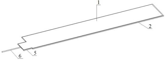
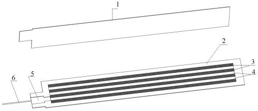
[0041] Such as Figure 1 to Figure 5 Shown is the first embodiment of the ultra-thin flat heat pipe of the present invention, which includes a base plate 2 and a cover plate 1 snap-fit ​​package, the base plate 2 is provided with a concave cavity with a number of capillary structures arranged in parallel, and the adjacent capillary structures A gas flow channel 7 for the flow of the working fluid of the heat pipe is formed between them, and the capillary structure includes several liquid flow channels arranged in parallel.

[0042] When this embodiment is implemented, the setting of the capillary structure can provide greater capillary force on the one hand, and can be used as the internal support structure of the flat heat pipe on the one hand to prevent the heat pipe from collapsing and deforming; the setting of placing the capillary structure in the concave cavity can Reduce the thickness of the flat heat pipe; the gas working medium flows in the gas flow channel 7, and the...

Embodiment 2

[0047] This embodiment is an embodiment of the manufacturing process of the ultra-thin flat heat pipe, comprising the following steps:

[0048] S10. Etching a concave cavity on the base plate 2;

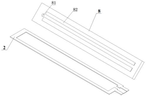
[0049] S20. Place the screen in the concave cavity of the base plate 2, and press it with a graphite plate after spraying alcohol to make the screen closely fit the base plate 2, and place it in a sintering furnace filled with an inert gas for primary sintering;

[0050] S30. After naturally cooling the bottom plate 2 sintered in step S20, fill it with sintered powder, and place it in a sintering furnace filled with inert gas for secondary sintering to form gas flow channels 7 and liquid flow channels;

[0051] S40. Put the cover plate 1 and the base plate 2 opposite to each other and package them;

[0052] S50. Vacuumize the heat pipe and fill it with working fluid, and seal the tail of the liquid-filled pipe 6 .

[0053] Wherein, in step S10, the depth of the concave cavity is 0....


PUM


Abstract

The present invention relates to the technical field of heat dissipation devices, and more specifically relates to an ultra-thin flat heat pipe and its manufacturing process, including a bottom plate and a cover plate snap-fitted and packaged, and the bottom plate is provided with concave holes with several capillary structures arranged in parallel. In the cavity, a gas flow channel for the flow of the working fluid of the heat pipe is formed between adjacent capillary structures, and the capillary structure includes several liquid flow channels arranged in parallel. The gas working medium flows in the gas flow channel, and the liquid working medium flows in the capillary structure, so as to realize the gas-liquid separation of the working medium, reduce the flow resistance, and improve the heat transfer limit of the heat pipe; and the invention has simple structure and simple manufacture, and can It realizes industrial assembly line production, and has strong heat transfer capacity. The thickness of the heat pipe is small, which can meet the heat dissipation of electronic devices in narrow spaces, and meet the needs of integration and miniaturization of electronic components. It has good practicability and applicability. .

Description

technical field [0001] The present invention relates to the technical field of heat dissipation devices, and more particularly relates to an ultra-thin flat heat pipe and a manufacturing process thereof. Background technique [0002] Since entering the 21st century, electronic technology and information industry have developed rapidly. The miniaturization and integration of electronic devices has become the development trend of electronic technology. The high integration, high packaging density and high operating frequency of electronic chips make the temperature of the chip rise rapidly. . Studies have shown that the damage rate of electronic components is positively correlated with the operating temperature. When electronic components are under high-temperature operating conditions for a long time, their reliability will decrease significantly. According to statistics, about 55% of the failures of electronic devices are caused by overheating. The normal operating tempera...

Claims


Application Information

Patent Timeline
Patent Type & Authority Patents(China)
IPC IPC(8): F28D15/04
CPCF28D15/046
Inventor 朱明汉黄金胡艳鑫陈木生王婷陈永贵
Owner GUANGDONG UNIV OF TECH
Why Eureka
Try Eureka