Surface-enhanced Raman spectroscopy-based photocatalytic in-situ monitoring system

A surface-enhanced Raman and monitoring system technology, applied in spectrometry/spectrophotometry/monochromator, Raman scattering, optical radiation measurement, etc., can solve the problems affecting the accuracy of the monitoring process, focus point monitoring error, Increase the difficulty of the experiment and other problems to achieve the effect of avoiding the change of the concentration of the reaction solution and improving the accuracy

Active Publication Date: 2019-03-08
DONGGUAN UNIV OF TECH
View PDF14 Cites 4 Cited by
  • Summary
  • Abstract
  • Description
  • Claims
  • Application Information

AI Technical Summary

Problems solved by technology

In this Raman in-situ monitoring method, the thin layer of reaction solution on the surface of the solid SERS substrate is volatile under the irradiation of Raman excitation light, which causes the concentration of the reaction solution to change, thus affecting the accuracy of the monitoring process.
[0006] Since the incident light path of the photocatalytic light source and the Raman excitation light path of the above two methods are not in the same path, in order to realize the monitoring of the photocatalytic process, it is necessary to adjust the focal point coincidence of the two paths of light, which not only greatly increases the difficulty of the experiment, but also has the Monitoring errors caused by incomplete coincidence of focus points

Method used


Image

  • Surface-enhanced Raman spectroscopy-based photocatalytic in-situ monitoring system
  • Surface-enhanced Raman spectroscopy-based photocatalytic in-situ monitoring system

Examples


Embodiment Construction

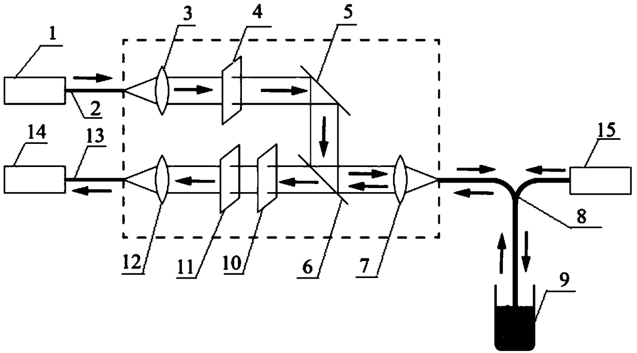
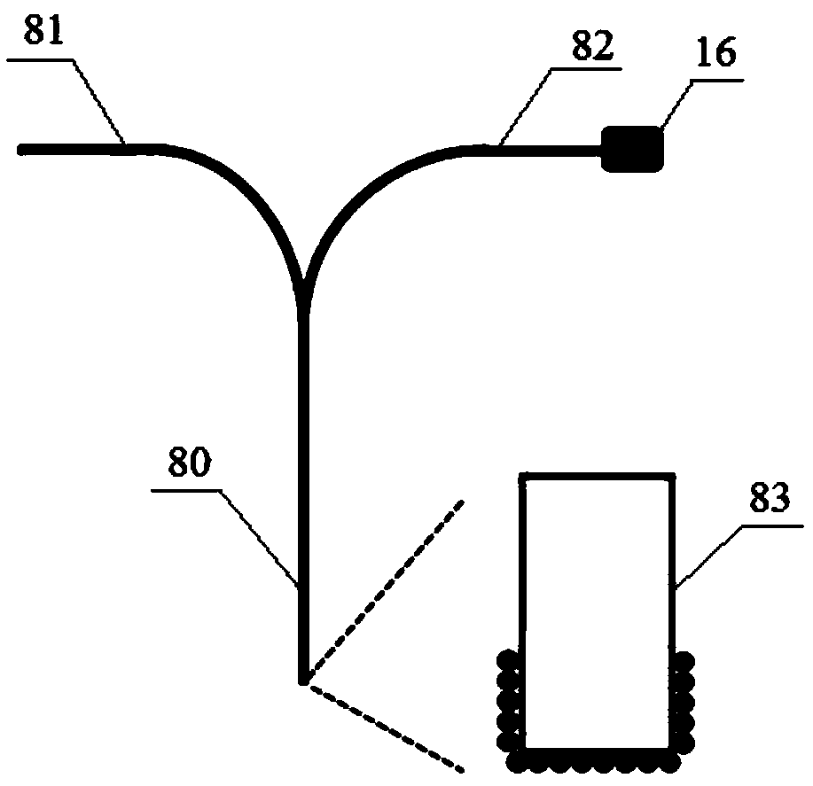
[0027] The following will clearly and completely describe the technical solutions in the embodiments of the present invention with reference to the accompanying drawings in the embodiments of the present invention. Obviously, the described embodiments are only some, not all, embodiments of the present invention. Based on the embodiments of the present invention, all other embodiments obtained by persons of ordinary skill in the art without making creative efforts belong to the protection scope of the present invention.

[0028] The purpose of the present invention is to provide a photocatalytic in-situ monitoring system based on surface-enhanced Raman spectroscopy. The Raman excitation light and photocatalytic light can be transmitted in the same path, and there is no need to adjust the focus point during photocatalytic monitoring, which not only greatly improves the The difficulty of the experiment is reduced, and the monitoring error caused by incomplete coincidence of the fo...


PUM

PropertyMeasurementUnit
angleaaaaaaaaaa
wavelengthaaaaaaaaaa
widthaaaaaaaaaa

Abstract

The invention discloses a surface-enhanced Raman spectroscopy-based photocatalytic in-situ monitoring system. The monitoring system comprises a Raman excitation light source, a laser coupling lens, anarrow band filter, a total reflection mirror, a dichroic mirror, a focus coupling lens, a surface enhanced Raman scattering fiber probe, a liquid phase photocatalytic reactor, a photocatalytic lightsource, a Raman collection lens and a spectrometer, wherein one end of a common detecting portion of the surface-enhanced Raman scattering fiber probe extends to from a first branching portion and a second branching portion; the extending end of the first branching portion is coupled to the focus coupling lens, and the extending end of the second branchingportion is coupled with the photocatalyticlight source; the other end of the common detecting portion is disposed in the liquid phase photocatalytic reactor; and a Raman excitation light and a photocatalytic light are in co-transmission, which greatly reduces the experimental difficulty and can effectively avoid a monitoring error caused by incomplete coincidence of focus points, thereby effectively improving the accuracy of Raman dynamic monitoring. The monitoring system is compact in structure and high in portability.

Description

technical field [0001] The invention relates to the field of photocatalytic in-situ monitoring, in particular to a photocatalytic in-situ monitoring system based on surface-enhanced Raman spectroscopy. Background technique [0002] Photocatalytic chemical reaction refers to a type of chemical reaction carried out by photocatalytic materials (such as TiO2) under ultraviolet or visible light irradiation, such as photocatalytic hydrolysis for hydrogen production, photocatalytic degradation of organic matter, etc., and has important applications in energy, environment and other fields. The photocatalytic reaction mechanism and photocatalyst selection have an important impact on the chemical reaction speed and efficiency. The dynamic monitoring of the photocatalytic chemical reaction process is the premise of understanding the photocatalytic reaction mechanism and designing high-efficiency photocatalysts, which has become a current research hotspot. [0003] Photocatalytic chemi...

Claims


Application Information

Patent Timeline
Patent Type & Authority Applications(China)
IPC IPC(8): G01N21/65
CPCG01N21/65G01N21/658G01N2021/655B01J19/0093B01J35/004B01J2219/0097B01J2219/00975G01J3/0227G01J3/44G01N21/8507G01N2021/475G01N2021/656G01N2021/8411G01N2021/8528G02B27/141B01J19/123C02F2305/10G01N2201/06113G01N2201/062G01N2201/0633G01N2201/0636G01N2201/08G02B5/20
Inventor 周飞刘晔凌东雄王红成
Owner DONGGUAN UNIV OF TECH
Why Eureka
Try Eureka